
Metal terminal block adapted for surface mounting and method of mounting the same

A metal wiring and surface mount technology, which is applied in the field of metal wiring terminals, can solve the problems of thin flexible printed circuit board, weak welding strength, and large contact resistance, etc., and achieve the effect of enlarged grounding area, easy welding, and easy welding

Active Publication Date: 2013-07-03
JOINSET +2
View PDF4 Cites 3 Cited by
  • Summary
  • Abstract
  • Description
  • Claims
  • Application Information

AI Technical Summary

Problems solved by technology

As a result, it is not convenient to directly solder the metal core wire of a small-sized cable to the conductive pattern on the printed circuit board, especially when the size of the conductive pattern of the printed circuit board is small, the welding strength between the metal core wire and the conductive pattern Disadvantages of weak and large contact resistance
[0006] In particular, there is a disadvantage that it is not convenient to solder with the metal core wire of the cable because the printed circuit board is roughly formed as a plane
[0007] Furthermore, for a printed circuit board that is applied to a situation where the grounding area is small like a printed circuit board for a mobile phone, when its conductive pattern is used as a ground pattern, there is a problem that it is difficult to increase due to the cable metal core wire soldered on the conductive pattern. Disadvantages of ground area
[0008] Moreover, in the case of using a coaxial cable for accurate signal transmission, the metal shielding material for shielding electromagnetic waves located immediately inside the sheath and the innermost metal core wire are connected to the printed circuit by soldering. On each plane conductive pattern separated on the board, it is not convenient for soldering, and since each conductive pattern is arranged adjacent to each other, an electrical short circuit may occur between the metal shielding material and the metal core wire according to the result of the welding operation
Although the distance between the metal shielding material and the metal core wire can be increased to prevent short circuits, however, since a large number of metal core wires that are not covered by the metal shielding material are exposed, the electromagnetic wave shielding effect is reduced and the function of the coaxial cable is reduced.
[0009] In addition, when the printed circuit board is a thin planar flexible board such as a flexible printed circuit board (FCCL), the material characteristics of the flexible circuit board determine that each conductive wire formed by manually soldering the metal core wire to the flexible printed circuit board There is bound to be a time limit on the pattern, and because of the poor mechanical strength of the flexible printed circuit board, there is a disadvantage of weak soldering strength with the conductive pattern of the flexible printed circuit board as a whole
In particular, since the thickness of the flexible printed circuit board is thin, the soldered part tends to fall off when it is directly soldered on it and moved or especially when bent
[0010] Moreover, when the metal leads of the electronic components are to be soldered on the conductive pattern of the printed circuit board, it is not convenient to manually solder each metal lead on the plane conductive pattern with a very narrow pitch on the printed circuit board and make the distance between the metal leads electrical separation

Method used


Image

  • Metal terminal block adapted for surface mounting and method of mounting the same
  • Metal terminal block adapted for surface mounting and method of mounting the same
  • Metal terminal block adapted for surface mounting and method of mounting the same

Examples


Embodiment Construction

[0043] Embodiments of the present invention will be described below with reference to the accompanying drawings.

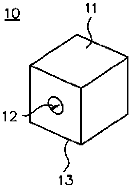
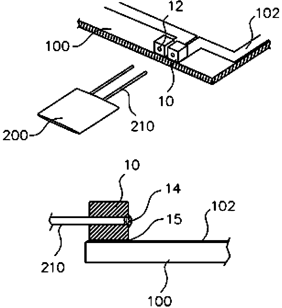
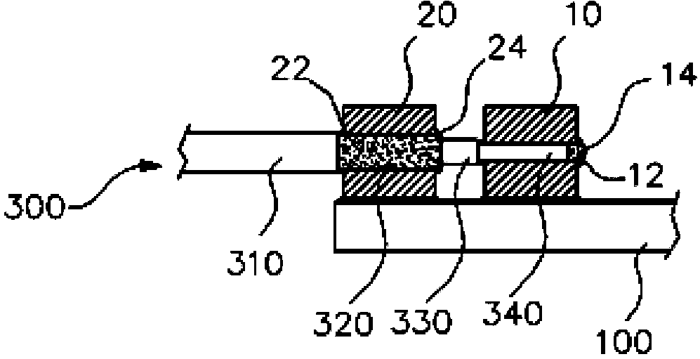
[0044] figure 1 Shown is a metal connection terminal 10 according to one embodiment of the present invention, figure 2 Shown are a state in which a metal terminal is applied to a circuit board and a state in which a metal lead of a thermistor as an electronic component is bonded to the metal terminal.

[0045] As shown in the figure, the metal connection terminal 10 has a three-dimensional shape, for example, a hexahedron shape, and the surface 11 and the bottom surface 13 are horizontal planes and formed of a single body of metal material. Since the bottom surface 13 is a horizontal plane, reflow soldering can be performed; since the surface 11 is a horizontal plane, surface mounting can be performed by vacuum pick-up.

[0046] Insertion holes 12 are formed through the front and rear sides to insert core wires of cables or metal leads of electronic components,...


PUM


Abstract

Provided is a metal terminal block adapted for surface mounting, which includes a metal body having a three-dimensional shape, an outer surface of which includes at least one portion appropriate for vacuum pickup. The metal terminal block provided on a reel carrier through taping is picked up through the vacuum pickup on the portion of the outer surface of the metal body and is mounted on a conductive pattern of a circuit board through the surface mounting. A back surface of the metal terminal block is adhered to the conductive pattern through reflow soldering. The metal body has an insertion recess extending from a surface to an opposite surface thereto, or an insertion hole passing through a surface to an opposite surface thereto.

Description

technical field [0001] The present invention relates to a metal terminal that can be surface mounted, and in particular to a surface mount by vacuum pick-up, so that reflow soldering can be performed on the conductive pattern of the printed circuit board, and it can be combined with the required cable A metal terminal for soldering metal core wires or metal leads of electronic components. Background technique [0002] In order to electrically connect the conductors of various cables such as coaxial cables to the conductive pattern of the printed circuit board, a metal core wire or a metal shielding material with a circular or quadrilateral cross-sectional shape inside the cable sheath is required. Solder with solder while being exposed and in direct contact with the conductive pattern on the printed circuit board. [0003] Some are in the state where the metal leads of the lead wires that are electrically connected to the electrical components such as thermistors and whose ...

Claims


Application Information

Patent Timeline
Patent Type & Authority Applications(China)
IPC IPC(8): H01R11/11H01R12/57H05K13/04
CPCH05K3/3405H05K3/3421H05K2201/1031H05K2201/10356H05K2201/10628H05K2201/10962Y02P70/50H05K1/181
Inventor 金镇山金瑞暻
Owner JOINSET
Learn More