Method for reconstructing dynamic fluorescence molecular tomography

A technology of fluorescent molecular tomography and fluorescent molecular imaging, which is applied in the field of reconstruction of fluorescent molecular tomographic images, can solve the problems of exceeding the computing power, exceeding the computing power of ordinary computers, occupying space-time weight matrix, etc., to reduce the calculation scale and make up for Time dependency considerations, effects of high data compression

Inactive Publication Date: 2013-07-03
TSINGHUA UNIV
View PDF6 Cites 10 Cited by
  • Summary
  • Abstract
  • Description
  • Claims
  • Application Information

AI Technical Summary

Problems solved by technology

However, in dynamic FMT imaging studies, such as in the study of drug metabolism, the concentration of the drug (fluorescent probe) changes with time, so each frame of measurement data (fluorescence projection image) collected is time-dependent. Highly correlated, if the above-mentioned frame-by-frame reconstruction method is used for 4D FMT reconstruction of fluorescence projection images, the correlation of the concentration of fluorescent probes along the time axis during the reconstruction process is ignored, but if all the collected fluorescence projection image sequences are directly used as a The overall direct 4D reconstruction, the amount of calculation usually exceeds the computing power of ordinary computers, for example, for a 35-frame fluorescence projection image sequence (assuming that 24 fluorescence projection images from different angles are collected at equal intervals during each frame of FMT imaging) For direct 4D FMT reconstruction, the space-time weight matrix used for reconstruction will occupy about 3234GB of memory, which greatly exceeds the computing power of ordinary computers

Method used


Image

  • Method for reconstructing dynamic fluorescence molecular tomography
  • Method for reconstructing dynamic fluorescence molecular tomography
  • Method for reconstructing dynamic fluorescence molecular tomography

Examples


Embodiment Construction

[0018] The present invention will be described in detail below in conjunction with the accompanying drawings and embodiments.

[0019] For FMT imaging, based on the first-order Born approximation, the fluorescence projection image acquired at the detection point r can be expressed by the following formula:

[0020] Φ m (r)=∫ r′∈V G(r,r')n(r')Φ x (r')dr' (1)

[0021] In the formula, V is the reconstruction area; Φ x is the light field distribution function, which describes the photon density corresponding to the excitation light wavelength, Φ m is the photon density of the emission (fluorescence) wavelength; n(r′) is the fluorescence yield to be reconstructed at the point r′ in the reconstruction area V, usually n(r′) is proportional to the concentration of the fluorescent probe; Green’s function G( r, r') describe the propagation of photons in the imaging object in the fluorescence band.

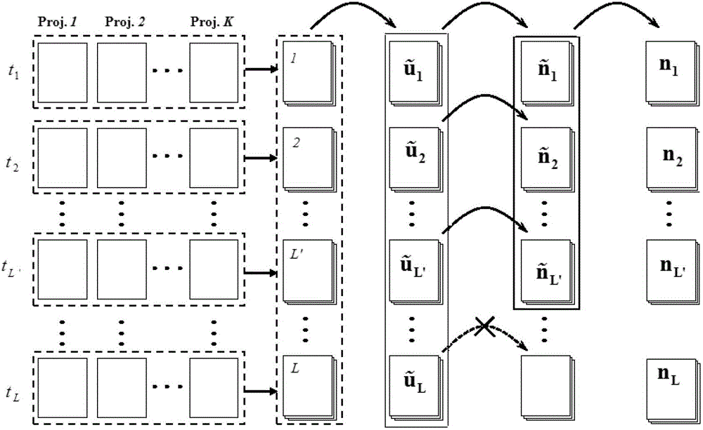
[0022] For dynamic FMT, after the reconstruction area V is discretized into a smal...


PUM


Abstract

The invention relates to a method for reconstructing a dynamic fluorescence molecular tomography. The method comprises the following steps of: 1) arranging a small animal-induced fluorescence molecular tomography system; 2) adopting the system to collect fluorescence projected image which reflects the metabolic distribution of a fluorescence probe in an imaging target in a full-angle and equal-interval manner at different time points and storing an acquired image as an input matrix u; 3) generating a KL transformational matrix A based on u; 4) calculating data after the input matrix u is transformed through KL; 5) obtaining L' KL components for 3D reconstruction after KL transformation; 6) generating a weight matrix W1 according to an optical field distribution function Phi x and a green function G; 7) performing 3D reconstruction on each KL component by adopting a 3D FMT reconstruction method according to a formula shown in the description; 8) and performing inverse KL transformation to reconstruction results of the KL components to obtain 4D fluorescence fault sequence. The invention can be widely applied to the reconstruction process of the dynamic fluorescence molecular tomography.

Description

technical field [0001] The invention relates to a method for reconstructing a fluorescent molecular tomographic image, in particular to a method for reconstructing a dynamic fluorescent molecular tomographic image. Background technique [0002] At present, the reconstruction of dynamic (4D) fluorescent molecular tomographic images is mostly completed by frame-by-frame reconstruction method, that is, the collected fluorescence projection images of each frame (circle) are reconstructed one by one. The advantage of this method is that it can directly use various existing induced fluorescence molecular tomography (Fluorescence Molecular Tomography, FMT) reconstruction methods to complete image reconstruction. However, in dynamic FMT imaging studies, such as in the study of drug metabolism, the concentration of drugs (fluorescent probes) changes with time, so each frame of measurement data (fluorescence projection images) collected is time-dependent. Highly correlated, if the ab...

Claims


Application Information

Patent Timeline
Patent Type & Authority Applications(China)
IPC IPC(8): A61B5/00
CPCG06T11/006G01N21/64G06T2211/412
Inventor 白净刘欣张宾
Owner TSINGHUA UNIV
Why Eureka
Try Eureka