Electronic component welding method

A technology of electronic components and welding methods, which is applied in the direction of assembling printed circuits with electrical components, welding equipment, manufacturing tools, etc., and can solve problems such as virtual soldering, easy cold soldering of products, and difficulty in heating solder paste

Inactive Publication Date: 2013-07-10
SHANGHAI AMPHENOL AIRWAVE COMM ELECTRONICS CO LTD
View PDF5 Cites 5 Cited by
  • Summary
  • Abstract
  • Description
  • Claims
  • Application Information

AI Technical Summary

Problems solved by technology

It is very difficult to heat the solder paste itself, and the product is prone to defects such as cold welding and virtual welding.

Method used


Image

  • Electronic component welding method
  • Electronic component welding method
  • Electronic component welding method

Examples


Embodiment

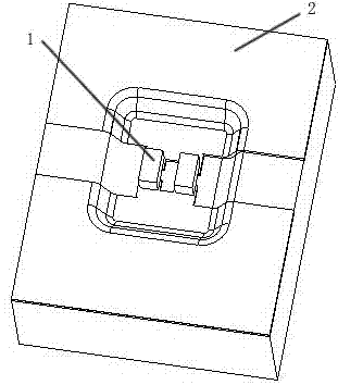
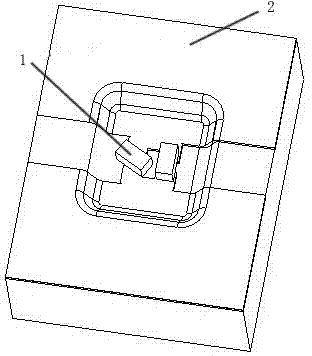
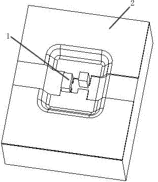
[0030] A welding method for electronic components 1, comprising the following steps:

[0031] First, do a pit structure treatment at the position of the carrier 2 where the component 1 needs to be welded to obtain a pit that matches the structure of the component 1;

[0032] Then, place the component 1 in the pit, and then apply the solder paste 3 on the top of the component 1 and between the component 1 and the side wall of the pit;

[0033] The solder paste 3 is heated, and the solder paste 3 absorbs the heat and solidifies to complete the soldering.

[0034] The volume of the pit is larger than the volume of the component 1, which heats the solder paste 3 through a reflow soldering furnace, and the carrier 2 includes a PCB and a plastic body, and can also be a carrier 2 of other materials. List them all. The surface of the carrier 2 is a profiled surface, that is, an uneven surface.

[0035] It heats the solder paste 3 through a reflow soldering furnace, the pre-solderin...


PUM


Abstract

The invention discloses an electronic component welding method. The method comprises the following steps: firstly, subjecting the carrier of an electronic component to the pit structural processing to obtain a pit which is matched with the structure of the electronic component; secondly, placing the electronic component inside the pit and coating solder paste on the top of the electronic component and between the electronic component and the side wall of the pit; and thirdly, heating the solder paste to be melted to complete the welding process. By forming the pit structure on the carrier, defects such as excursion and tombstoning can be avoided due to the structure limit when the electronic component is placed inside the pit; without the blocking of the electronic component, the solder paste can absorb heat easily to be melted for welding; and by means of the top welding, a production line operator can be facilitated to detect and judge the welding quality.

Description

technical field [0001] The invention relates to a surface mounting process of electronic components, specifically soldering electronic components on PCBs, plastic bodies or other carriers. Background technique [0002] The common surface mount process is mostly to pre-add solder paste on the surface of FPC or PCB and melt the solder paste through the reflow soldering process, so as to achieve the purpose of soldering / mounting components on FPC or PCB. But with the development of technology, the soldering of components is not limited to the flat planes of FPC&PCB, such as attached Figure 1 As shown, due to the needs of product design, more and more components are required to be soldered on some special-shaped (non-flat) surfaces. as attached Figure 1 The main technical bottleneck encountered in the existing process of welding electronic components in the pit shown is: [0003] 1. Because it is a special-shaped surface, not a flat surface. Therefore, the traditional st...

Claims


Application Information

Patent Timeline
Patent Type & Authority Applications(China)
IPC IPC(8): B23K1/008H05K3/34
Inventor 张文宇蒋元魁翟后明丁迎伟姚巍巍
Owner SHANGHAI AMPHENOL AIRWAVE COMM ELECTRONICS CO LTD
Why Eureka
Try Eureka