Blast furnace top chute distributing device

A blast furnace and distributor technology, applied in blast furnace, blast furnace details, blast furnace parts, etc., can solve problems such as unsuitable realization, asynchronous processing and assembly, short life of distributor, etc., to overcome the difficulty of processing, prolong service life, The effect of a short drive chain

Active Publication Date: 2013-07-24
QINHUANGDAO QINYE HEAVY IND
View PDF9 Cites 4 Cited by
  • Summary
  • Abstract
  • Description
  • Claims
  • Application Information

AI Technical Summary

Problems solved by technology

The distribution device of the planetary differential transmission has a complex structure, high equipment price, maintenance and repair costs, difficult equipment manufacturing, poor equipment process performance and high temperature resistance performance of the furnace roof; single oil cylinder and steel wire rope combined transmission, servo motor and steel wire rope combined transmission The wire rope system of the device is complex, and the wire rope is prone to fatigue and fracture. The chute is lifted by the counterweight of the translation support ring. The structure has certain limitations, and it is not suitable for large blast furnaces. The lever-driven distributor has two lifting points and four lifting points. , regardless of the form, there are problems of mechanical over-constraint and asynchronous processing and assembly, resulting in a short life of the distributor and failing to meet the requirements of a generation of furnace life

Method used


Image

  • Blast furnace top chute distributing device
  • Blast furnace top chute distributing device
  • Blast furnace top chute distributing device

Examples


Embodiment Construction

[0069] The present invention will be described in further detail below in conjunction with the accompanying drawings and specific embodiments, but not as a limitation of the present invention.

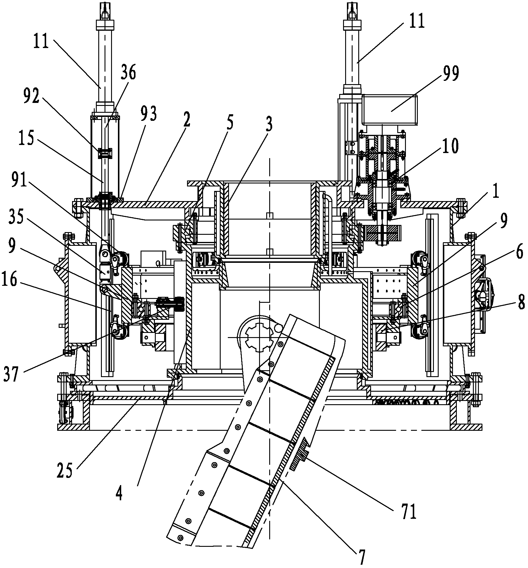
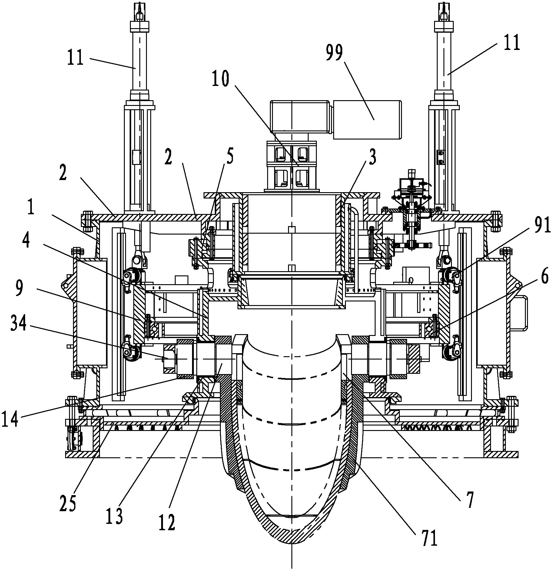
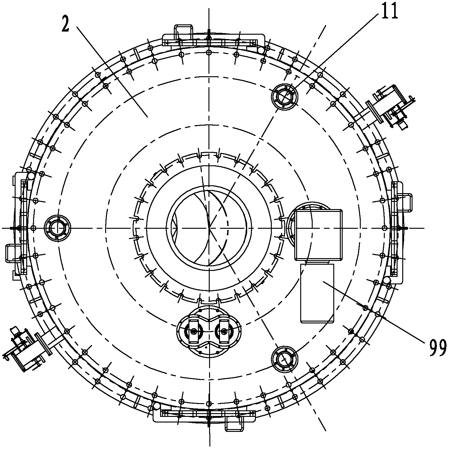
[0070] figure 1 It is a schematic diagram of the overall structure of the blast furnace top chute distributor of the present invention; figure 2 It is a schematic diagram of the overall structure in another direction of the blast furnace roof chute distributor of the present invention; image 3 for figure 2 top view of Figure 4 It is a schematic diagram of the connection structure of the universal frame of the blast furnace roof chute distributor of the present invention, the lower slewing bearing inner ring and the chute bracket; Figure 1 to Figure 4 As shown, the blast furnace roof chute distributor of the present invention includes an airtight box 1, a top cover 2, a throat 3, a rotating sleeve 4, an upper slewing bearing 5, a lower slewing bearing 6, a chute 7, and a univers...


PUM


Abstract

The invention discloses a blast furnace top chute distributing device. The device comprises an airtight casing, a choke, an upper slewing bearing, a rotary sleeve, a chute, an universal frame, a lower slewing bearing, a star wheel assembly, oil cylinders and a horizontal driver used for driving the upper slewing bearing to rotate, and the choke traverses a top cover arranged at the top of the airtight casing; the inner ring of the upper slewing bearing is connected with the top cover; the rotary sleeve is connected with the outer ring of the upper slewing bearing, the rotary sleeve is provided with trunnions, and the chute is suspended in the rotary sleeve through the trunnions; the trunnions are connected with one end of a crank; the other end of the crank is arranged in the chute of the universal frame; the inner ring of the lower slewing bearing is connected with the universal frame; one end of the star wheel assembly is connected with the inner ring of the lower slewing bearing, and the other end of the star wheel assembly is positioned in the sliding slots of the rotary sleeve; and the oil cylinders are used for dragging the lower slewing bearing to move up and down. The blast furnace top chute distributing device has the advantages of reasonable structure, long service life, shortest driving chain, stable running, and no lateral force to a guide rail.

Description

technical field [0001] The invention relates to a furnace top charging device for a smelting blast furnace, in particular to a blast furnace top chute distributor. Background technique [0002] Blast furnace top charging equipment is the key equipment for blast furnace ironmaking. Whether the equipment can meet the technological requirements directly restricts the output of blast furnace. Since blast furnace ironmaking, blast furnace top charging equipment has experienced the following three generations of development. The first generation is bell-type furnace top charging equipment; the second generation is furnace top charging equipment with material bell and movable throat baffle; the third generation is furnace top charging equipment without material bell. With the development and progress of the iron and steel industry, in the past two decades, especially in the past ten years, the blast furnace roof charging equipment has gradually replaced the bell-type furnace roof ...

Claims


Application Information

Patent Timeline
Patent Type & Authority Applications(China)
IPC IPC(8): C21B7/00C21B7/20
CPCC21B7/20C21B7/18F27B1/20C21B5/008C21B7/205F27D3/10
Inventor 陈晓光许振东兰大伟
Owner QINHUANGDAO QINYE HEAVY IND
Why Eureka
Try Eureka