Half-direct-driven wind power transmission system

A transmission system, semi-direct drive technology, applied in the field of transmission system, can solve the problems of poor installation alignment between generator and gearbox, large space occupation, high failure rate, etc., to reduce the load on the machine head, reduce the space occupied, and reduce the service life long effect

Inactive Publication Date: 2013-07-24
DALIAN UNIV OF TECH
View PDF6 Cites 3 Cited by
  • Summary
  • Abstract
  • Description
  • Claims
  • Application Information

AI Technical Summary

Problems solved by technology

Existing megawatt-level wind turbines are mainly equipped with gearboxes, and the speed increaser adopts three-stage transmission, two-stage planetary gear system and one-stage parallel shaft system. The structure is complex, requiring high machining accuracy and high transmission ratio. The failure rate is high, the volume is large, the space is large, the vibration is large, and the cost is high. The generator adopts an asynchronous motor, and the gearbox and the generator are installed on the chassis of the engine room at the same time. The installation alignment between the generator and the gearbox is poor and takes up a lot of space

Method used


Image

  • Half-direct-driven wind power transmission system
  • Half-direct-driven wind power transmission system
  • Half-direct-driven wind power transmission system

Examples


Embodiment 1

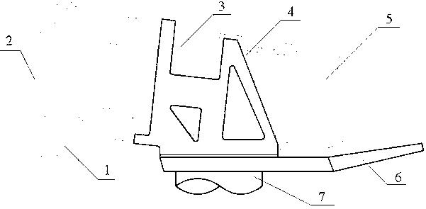
[0021] Such as figure 1 As shown, the whole machine is mainly divided into 3 large modules, hub rotor assembly module 3, gear box assembly module 4 and generator assembly module 5. Other structures also include blade 1, hub 2, nacelle base 6 and tower 7. The hub 2 is connected to the blade 1 by bolts, and the energy acting on the blade 1 is transferred to the hub 2. Inside the hub rotor assembly module 3, the hub 2 is connected to the main shaft by bolts; the generator module 5 is directly assembled in the gear box assembly On the module 4, the gear box is fixed on the base 6 of the nacelle. The gearbox assembly module 4 and the generator assembly module 5 are installed integrally, the output end of the gearbox assembly module 4 is connected to the input end of the generator assembly module 5, the output end of the gearbox assembly module 4 and the input end of the generator assembly module 5 are on the same axis, After the gearbox assembly module 4 and the generator assembly m...

Embodiment 2

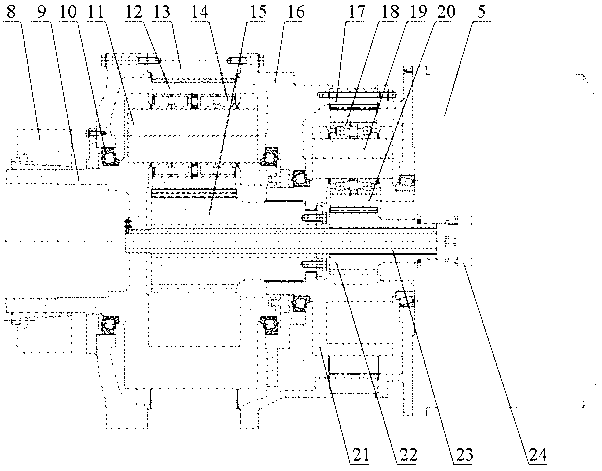
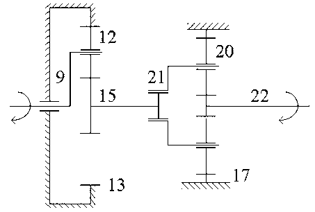
[0023] Such as figure 2 As shown, the speed increaser adopts a two-stage NGW planetary gear system, and the main shaft is connected to the first-stage planet carrier 9 inside the gear box through the locking disk 8, and then transmits energy to the first-stage planet carrier 9; 9 As the input of the speed increaser, it is supported on the box 16 through the tapered roller bearing 10. The planet carrier and the planetary gear shaft are interference fit, so the energy is transmitted to the first-stage planetary gear shaft 11; The first-stage planetary gear 12 is supported on the first-stage planetary gear shaft 11 through a double-row cylindrical roller bearing 14 and meshes with the first-stage inner ring gear 13, which is fixed on the box 16 by screws , Under the action of the first-stage planetary gear shaft 11, the rotation and revolution of the first-stage planetary gear 12 are realized; the first-stage planetary gear 12 is externally meshed with the first-stage sun gear sha...


PUM


Abstract

The invention provides a half-direct-driven wind power transmission system of a transmission system for a wind driven generator. A gear case assembly module and a generator assembly module are integrally arranged. An output end of the gear case assembly module is connected with an input end of the generator assembly module. An output end of the gear case assembly module and the input end of the generator assembly module are in the same axis. The gear case assembly module and the generator assembly module are connected and the center is located on a tower. According to the structure that a gear case is installed on a cabin chassis, the center of gravity is centralized, machine head loading is reduced, the shortage that the joint of a cabin and a hub is abraded is avoided, vibration of a cabin base is reduced, installation of the gear case and the generator can be achieved on the ground and lifting is convenient. An NGW planetary gear train is adopted by the speed changing box so that the half-direct-driven wind power transmission system has the advantages of being compact in structure, small in size and weight, large in carrying capacity, low in operation noise, high in efficiency, long in service life, capable of reducing a high-speed level, enabling the structure to be compact, reducing occupied space of the gear case and a reducing failure rate of the gear case and the like.

Description

Technical field [0001] The invention relates to a transmission system, especially a transmission system for a wind generator. Background technique [0002] Domestic wind turbines mainly include permanent magnet direct-drive wind turbines and double-fed wind turbines. The main difference between the two is the use of a gearbox. [0003] In terms of power generation capacity, permanent magnet direct-drive wind turbines do not have gearboxes, reducing transmission components, so the mechanical efficiency is improved, and the output power is greater at rated low speeds. However, because permanent magnet direct-drive units use full-power converters, The capacity is about 3 times that of the doubly-fed unit, so the electrical loss is greatly increased, and the energy consumption of the cooling system of the converter is also correspondingly increased. In order to reduce the phenomenon of permanent magnet demagnetization, the generator cooling system is more complicated and the energy co...

Claims


Application Information

Patent Timeline
Patent Type & Authority Applications(China)
IPC IPC(8): F03D11/02F16H57/023
CPCY02E10/72
Inventor 魏静孙伟王洋
Owner DALIAN UNIV OF TECH
Why Eureka
Try Eureka