Mounting and dismounting mechanism for electrombile battery and mounting and dismounting method thereof

A technology for electric vehicle batteries and loading and unloading mechanisms, which is applied in the direction of electric power devices, power devices, vehicle components, etc., and can solve problems such as danger, long battery replacement time, and low replacement efficiency

Active Publication Date: 2013-07-31
BIT HUACHUANG ELECTRIC VEHICLE TECH
View PDF8 Cites 10 Cited by
  • Summary
  • Abstract
  • Description
  • Claims
  • Application Information

AI Technical Summary

Problems solved by technology

However, there is a common problem in pure electric vehicles powered by rechargeable batteries. The charging time of ordinary vehicle batteries takes several hours, and they cannot quickly complete energy replenishment at gas stations like other oil and gas fuels, thus greatly limiting electric vehicles. the popularity of
[0003] In order to solve the above problems, the patent application No. 200810006771.6 proposes a method and device for quickly replacing large-scale battery packs. These methods generally use so-called high-voltage battery packs or full-voltage battery packs as replacement units to achieve rapid replacement of the entire battery pack. It is easy to install and unload, easy to maintain, expands the mileage, and is suitable for separate charging; but the invention does not realize automatic replacement, because most of the power batteries are lithium-ion polymer batteries, which have relatively high energy density and relatively large mass. Moreover, it belongs to the category of high-voltage electricity, and there is a certain danger in manual operation.
In addition, the existing quick-change system still needs a lot of manual inspection after the battery replacement is completed, and the reliability is not enough, so the battery replacement time is relatively long
[0004] In order to realize automatic replacement, the patent application No. 20111015101.9 discloses a quick battery replacement device for electric vehicles, which includes a track fixed on the ground and a frame slidingly connected with the track, a base is provided at the bottom of the frame, and a The pallet, the base and the pallet are provided with a lifting mechanism, and the battery positioning mechanism is also provided on the electric vehicle battery quick replacement device, including a correction arm and a pressure rod. This invention provides a compact, accurate positioning electric The quick and automatic battery replacement device for automobiles can save trouble and effort to complete the battery replacement work; however, the automatic replacement device is suitable for electric vehicles that load and unload batteries from the bottom of the vehicle, but not for electric vehicles that are loaded and unloaded from the side of the vehicle body, and the battery box is in the Passively accept replacement, the replacement efficiency is still low
[0005] In order to further improve the efficiency of replacing the battery box, the patent application number 20111009392.9 discloses a method for replacing the battery box and a battery replacement fixture, which uses the battery replacement fixture to carry the battery box, and the battery replacement fixture is installed on a movable quick-change system , the quick-change system completes the transfer of the battery box; the battery box is pulled out from the electric vehicle or charging rack through the rodless cylinder, and the battery box is pushed from the battery changing fixture into the electric vehicle or charging rack; the battery changing fixture Open or lock the battery box by unlocking the cylinder; complete the process of replacing the battery box; but the above-mentioned clamps directly act on the battery box during the battery box replacement process, because it is difficult to standardize the specifications and models of the battery objectively. Especially when clamping, it is easy to be unstable or unable to clamp, which cannot meet the needs of electric energy supplementary mechanisms similar to gas stations; and the battery box is passively accepted for replacement, and there is still a need for automatic replacement. with a certain gap

Method used


Image

  • Mounting and dismounting mechanism for electrombile battery and mounting and dismounting method thereof
  • Mounting and dismounting mechanism for electrombile battery and mounting and dismounting method thereof
  • Mounting and dismounting mechanism for electrombile battery and mounting and dismounting method thereof

Examples


specific Embodiment 1

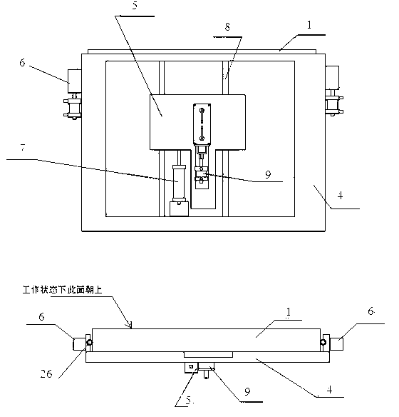
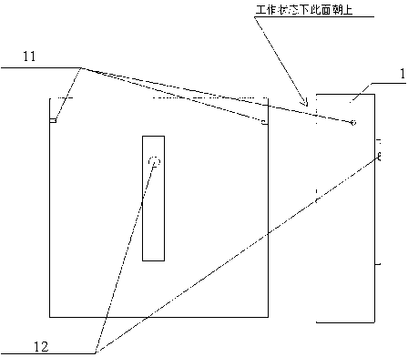
[0060]The pure electric vehicle power battery automatic quick-change battery box system connects the battery outer box 4, the battery inner box 1, the battery box locking and maintaining mechanism 6, the battery loading and unloading mechanism 5, and the battery quick-changing manipulator 21 through the cylinder control system 3. Together, an automated pure electric commercial vehicle power battery quick-change battery box system is formed. Through this system, the vehicle's battery box can be unlocked, the power battery inner box 1 can be automatically replaced, and the battery box is locked to complete the vehicle power battery. Automatic quick replacement; wherein the communication is wired communication or wireless communication; the cylinder control system 3 can complete the human-computer interaction, the battery box and the manipulator 21 information exchange, the battery box controls the locking and maintaining mechanism 6, and the battery loading and unloading mechanism...

specific Embodiment 2

[0067] On the basis of the above-mentioned specific embodiment 1, the positioning pin 17 is replaced by a photosensitive structure, and the sensing effect of the optical sensor is used to sense whether the battery inner box 1 is connected to the battery outer box 4 in place, so as to perform linkage The loading and unloading process of the battery inner box 1.

specific Embodiment 3

[0068] According to the battery loading and unloading mechanism of the pure electric vehicle power battery automatic quick-change battery box system of the specific embodiment, the specific loading and unloading method is as follows: when loading, when the tensioning cylinder 7 pulls the battery inner box 1 into the outer box In the assembly position, the positioning pin 17 can automatically enter the positioning pin hole at the bottom of the battery inner box 1 under the action of elastic force. At this time, the action of the locking cylinder 18 is triggered accordingly, and the locking pin 19 connects the battery inner box 1 with the battery outer box. The box 4 is locked; when the battery inner box 1 is unloaded, the cylinder control system 3 sends an unlocking signal to the signal receiving device of the locking cylinder 18, and correspondingly stimulates the locking cylinder 18 to take action, and at the same time the lock The tightening pin 19 and the positioning pin 17 ...


PUM


Abstract

The invention discloses a mounting and dismounting mechanism for an electrombile battery and a mounting and dismounting method thereof. An automatic fast-replacing battery box system of the pure electrombile power battery comprises a battery outer box, a battery inner box and a battery mounting and dismounting mechanism, wherein the battery inner box is placed inside the battery outer box; the battery outer box adopts a frame structure; a guide rail is arranged in the middle of the bottom casing of the battery outer box; a sliding structure matched with the guide rail is correspondingly arranged at the bottom of the battery inner box; the battery mounting and dismounting mechanism comprises a straining cylinder and a linkage mechanism; the straining cylinder is fixedly connected with the frame on one side of the battery outer box; the end part of a straining piston rod of the straining cylinder is connected with the corresponding position at the bottom of the battery inner box through an electromagnet; the straining cylinder is connected with the cylinder control system through an air channel control electromagnetic valve, and supplies power through the straining cylinder; the battery inner box can move along the guide rail; and the linkage mechanism is fixedly arranged at the bottom casing of the battery outer box, and moves in response to the movement of the straining cylinder.

Description

technical field [0001] The invention relates to a loading and unloading mechanism and a loading and unloading method, in particular to a battery loading and unloading mechanism and a loading and unloading method of a pure electric vehicle power battery automatic quick-change battery box system. Background technique [0002] With the development of society, energy is increasingly scarce, environmental pollution is serious, and the potential impact of global climate change is huge. Electric vehicles with diversified power sources and zero emissions have become the development direction of future vehicles. In the past, the power energy of vehicles mainly came from petroleum products and various gases. However, with the decreasing of oil and gas resources and the increasingly serious problems of noise pollution, air pollution and global warming, it is necessary to develop and utilize environmentally friendly alternative energy sources, reduce CO2 Emissions have become the consen...

Claims


Application Information

Patent Timeline
Patent Type & Authority Applications(China)
IPC IPC(8): B60S5/06
Inventor 林程周辉曲新起
Owner BIT HUACHUANG ELECTRIC VEHICLE TECH
Why Eureka
Try Eureka