Solar charger capable of charging various batteries
A technology of battery charging and solar energy, applied in battery circuit devices, current collectors, instruments, etc., can solve the problems that product functions cannot meet market demand, and achieve the effect of simple and reliable control circuit, convenient use, and strong versatility
- Summary
- Abstract
- Description
- Claims
- Application Information
AI Technical Summary
Problems solved by technology
Method used
Image
Examples
Embodiment 1
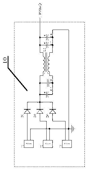
[0024] The specific circuit control mode of this embodiment is as follows, as Figure 3 to Figure 7 shown. The solar energy input parallel circuit module 10 includes three input interfaces J1, J2, J3, and anti-reverse diodes D1, D3, D5 are respectively connected to the positive terminals of the power supply, and they isolate the solar energy input from the input interface 1 and connect them to the common mode inductor On L2, at the same time, a large capacitor is connected to stabilize the front-end input.
[0025] The system power supply module 20 takes power directly from the rear end of solar energy input, and forms a step-down conversion circuit (Buck circuit) through triodes Q1, Q2, Q3, Q4, inductor L1, diodes D2, D4 and voltage regulator tube D7, and converts the input voltage to Stable to 12V to provide power for the DC / DC chip, the system power supply 20 is converted to 5V and 3.3V by the U1, U2 chip KB7550 and LM1117 conversion circuit, and supplies power to the char...
Embodiment 2
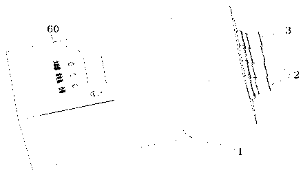
[0030] Example Figure 1-7 The shell of the box body 1 is an aluminum shell with a size of 135mm*97mm*45mm. The surface is anodized to achieve a certain anti-salt spray corrosion effect. It is equipped with three sets of flexible thin-film solar cell modules. The power is 100W. It is foldable and portable, suitable for field use . The plug-in PV input interface 2 is plugged with a multi-dimensional folded flexible solar cell module or a DC power supply provided by other transmitters.
[0031] How this charger works
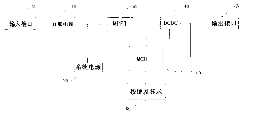
[0032] The system power supply module 20 takes power directly from the rear end of the solar input, and stabilizes the input voltage to 12V through the Buck circuit composed of transistors Q1, Q2, Q3, Q4, inductor L1, diodes D2, D4, and voltage regulator tube D7, which is DC / DC The chip provides power, and through KB7550 and LM1117 power IC, it is converted to 5V and 3.3V as the working power of IC.
[0033] The solar maximum power tracking circuit module 30 ad...
Embodiment 3
[0038] See Figure 1-7 , when the digital tube displays "5L" after the controller system of the present invention is started, the user can cycle select the battery type by short pressing the button (within 3 seconds) (the digital tube flashes at 1HZ during the selection process); by long pressing the button (greater than 3 seconds) to determine the battery type, after confirming the battery type, the digital tube stops flashing and displays the battery type for 10 seconds; then displays the remaining charging time, check the battery type: long press the button (more than 3 seconds) during charging to display the battery type.
[0039] The battery type and the corresponding digital tube display are as follows:
[0040] 1. 7.2V lithium-ion battery capacity of 1-2AH digital tube display: "L1"
[0041] 2. 14.4V lithium-ion battery with a capacity of 10AH, the digital tube display: "L2"
[0042] 3. The capacity of 12V alkaline storage battery is less than 0.6AH, and the digital t...
PUM
 Abstract
Description
Claims
Application Information
 - R&D
- Intellectual Property
- Life Sciences
- Materials
- Tech Scout
- Unparalleled Data Quality
- Higher Quality Content
- 60% Fewer Hallucinations
Browse by: Latest US Patents, China's latest patents, Technical Efficacy Thesaurus, Application Domain, Technology Topic, Popular Technical Reports.
© 2025 PatSnap. All rights reserved.Legal|Privacy policy|Modern Slavery Act Transparency Statement|Sitemap|About US| Contact US: help@patsnap.com


