Electro-hydraulic compound braking system based on hydraulic control unit and integrated braking master cylinder

A control unit, brake master cylinder technology, applied in the direction of brake transmission, brake, transportation and packaging, etc., can solve the problems of high manufacturing process requirements, complex control logic, high implementation cost, etc., to achieve scalability and applicability Good, the production process is simple, and the effect of improving braking efficiency

Inactive Publication Date: 2013-08-07
TONGJI UNIV
View PDF5 Cites 12 Cited by
  • Summary
  • Abstract
  • Description
  • Claims
  • Application Information

AI Technical Summary

Problems solved by technology

However, among the above-mentioned schemes, some of the improved structures are more complex and have extremely high requirements on the manufacturing process; some systems require complex control logic and high implementation costs; some still retain the vacuum booster, but need to add an additional vacuum pump

Method used


Image

  • Electro-hydraulic compound braking system based on hydraulic control unit and integrated braking master cylinder

Examples


Embodiment

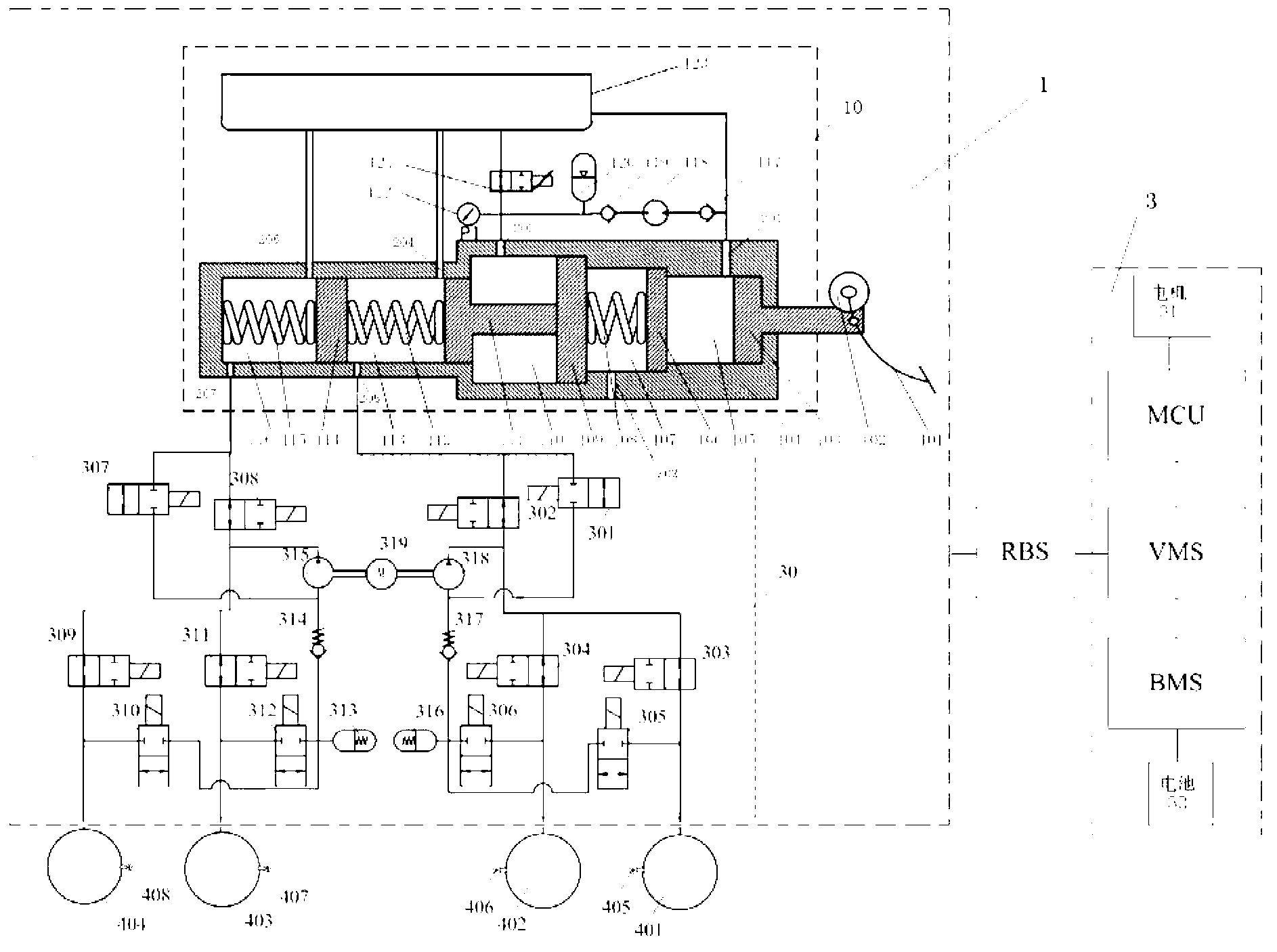
[0037] Such as figure 1 As shown, an electro-hydraulic hybrid braking system based on a hydraulic control unit and an integrated brake master cylinder includes a hydraulic brake subsystem 1, and the hydraulic brake subsystem 1 is composed of an integrated brake master cylinder assembly 10 Composed of a hydraulic control unit 30, the electro-hydraulic composite braking system also includes a composite braking control unit RBS and a motor feedback braking subsystem 3, the hydraulic braking subsystem 1, the composite braking control unit RBS and The motor regenerative braking subsystem 3 is connected sequentially, and the motor regenerative braking subsystem 3 is composed of a motor 31 , a motor controller MCU, a vehicle controller VMS, a battery management system BMS and a battery pack 32 .

[0038] Basic working principle: the composite brake control unit RBS collects the brake pedal displacement sensor 102 to obtain the driver's braking operation intention, and calculates the ...


PUM


Abstract

The invention relates to an electro-hydraulic compound braking system based on a hydraulic control unit and an integrated braking master cylinder. The system comprises a hydraulic braking subsystem (1), a compound braking control unit regenerative braking system (RBS) and a motor feedback brake subsystem (3) which are connected sequentially, and the hydraulic braking subsystem (1) comprises an integrated braking master cylinder assembly (10), a hydraulic control unit (30) and braking cylinders (401, 402, 403 and 404) which are connected sequentially. Compared with the prior art, the system has the advantages of being compact in structure, simple to implement and capable of flexibly adjusting the feeling of vehicle brake pedals, the system is provided with an active hydraulic boosting function under the normal brake condition and with a passive hydraulic boosting function under the failure condition, brake energy feedback can be achieved, and simultaneously, the system is provided with an anti-skid brake system (ABS) function, a traffic control station (TCS) function and an electronic stability program (ESP) function, so that the vehicle brake safety is guaranteed effectively.

Description

technical field [0001] The invention relates to an automobile brake system, in particular to an electro-hydraulic composite brake system based on an ESP / VCS / VSA / DSC / VSM hydraulic control unit and an integrated brake master cylinder. Background technique [0002] The powertrain of new energy vehicles such as pure electric vehicles, hybrid electric vehicles and fuel cell electric vehicles all use the motor-battery as the core to form an electric drive system. Energy recovery function. The use of regenerative braking can effectively recover the energy originally dissipated as heat energy during vehicle braking, and improve the energy utilization efficiency, fuel economy and emission performance of new energy vehicles. Since the motor feedback braking torque is limited by the external characteristics of the motor and the charging characteristics of the battery, it cannot meet the vehicle braking requirements on roads with high adhesion coefficient or high-speed emergency brakin...

Claims


Application Information

Patent Timeline
Patent Type & Authority Applications(China)
IPC IPC(8): B60T13/66
CPCB60T8/441
Inventor 孙泽昌刘杨王猛邢秀园李云鹏
Owner TONGJI UNIV
Why Eureka
Try Eureka