Linear electromagnetic damper with serially-connected magnetic circuit structure

A linear electromagnetic, series magnetic circuit technology, applied in the direction of magnetic springs, springs/shock absorbers, springs, etc., can solve the problem that the loading force cannot be continuously changed, and achieve the effect of eliminating the fluctuation of the loading force, high power density and low loss

Active Publication Date: 2013-08-07
HARBIN INST OF TECH
View PDF6 Cites 7 Cited by
  • Summary
  • Abstract
  • Description
  • Claims
  • Application Information

AI Technical Summary

Problems solved by technology

[0005] The present invention is to solve the problem that the existing linear motor thrust loading test device can only carry out the thrust loading on the mot

Method used


Image

  • Linear electromagnetic damper with serially-connected magnetic circuit structure
  • Linear electromagnetic damper with serially-connected magnetic circuit structure
  • Linear electromagnetic damper with serially-connected magnetic circuit structure

Examples


specific Embodiment approach 1

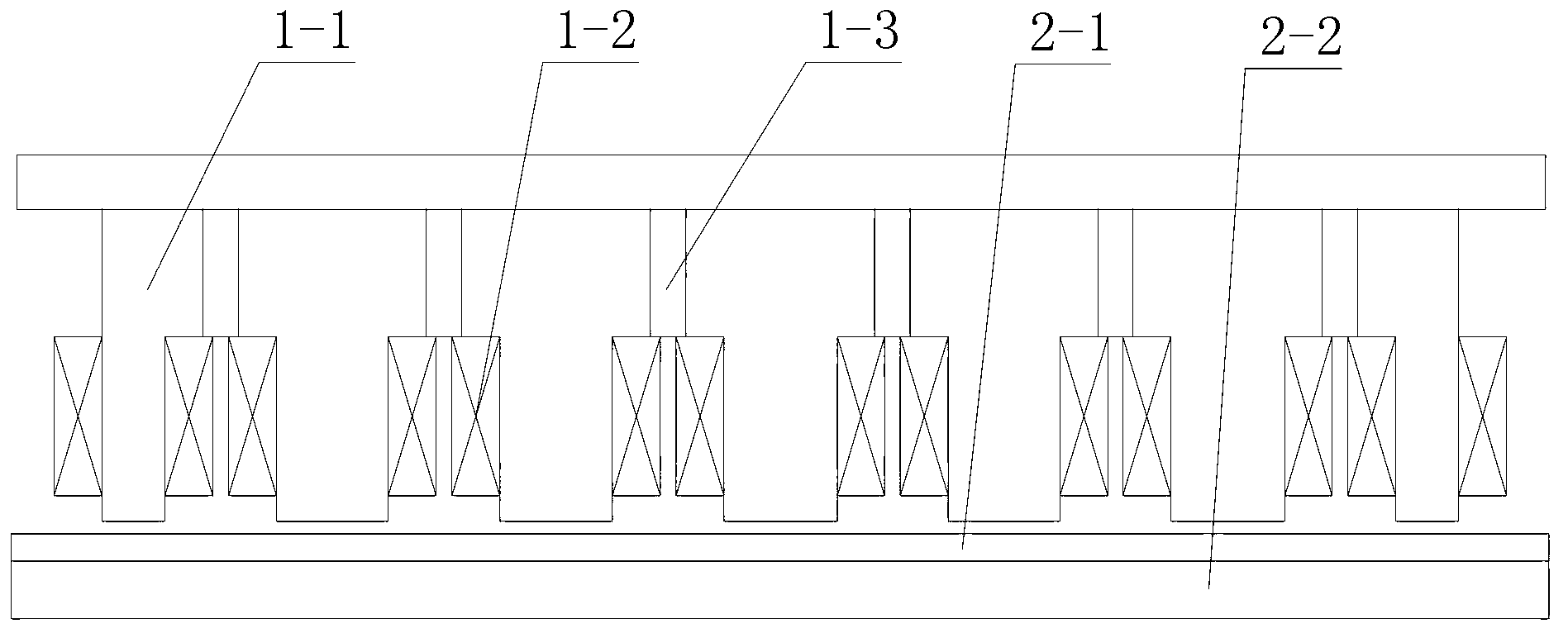
[0069] Specific implementation mode one: the following combination figure 1 Describe this embodiment mode, the linear electromagnetic damper of series magnetic circuit structure described in this embodiment mode, it comprises primary and secondary, is air gap between primary and secondary; Composed of 2n-1 primary permanent magnets 1-3, the air gap side surface of the primary iron core 1-1 is evenly opened with 2n-1 winding slots along the relative movement direction of the primary and secondary, so that the primary iron core 1-1 forms primary teeth A structure alternated with winding slots, the slotting direction of the winding slots is perpendicular to the relative movement direction of the primary and secondary, and n is a positive integer;

[0070] There is a coil wound on each primary tooth, the coils on the 1st, 3rd, 5th, ... and 2n-1 primary teeth are wound clockwise, and the coils on the 2nd, 4th, 6th, ... and 2n primary teeth The coil is wound counterclockwise, and ...

specific Embodiment approach 2

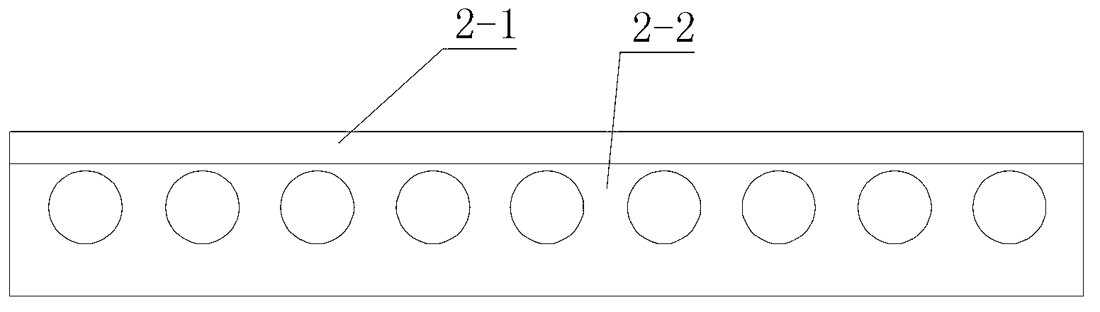
[0074] Specific implementation mode two: the following combination figure 2 Describe this embodiment, this embodiment will further explain Embodiment 1, the reaction plate 2-1 or the magnetic yoke plate 2-2 described in this embodiment are provided with parallel horizontal coolant channels;

[0075] The passage direction of the cooling liquid passage is parallel to the relative movement direction of the primary and secondary, and is evenly arranged along the slotting direction of the winding slots.

specific Embodiment approach 3

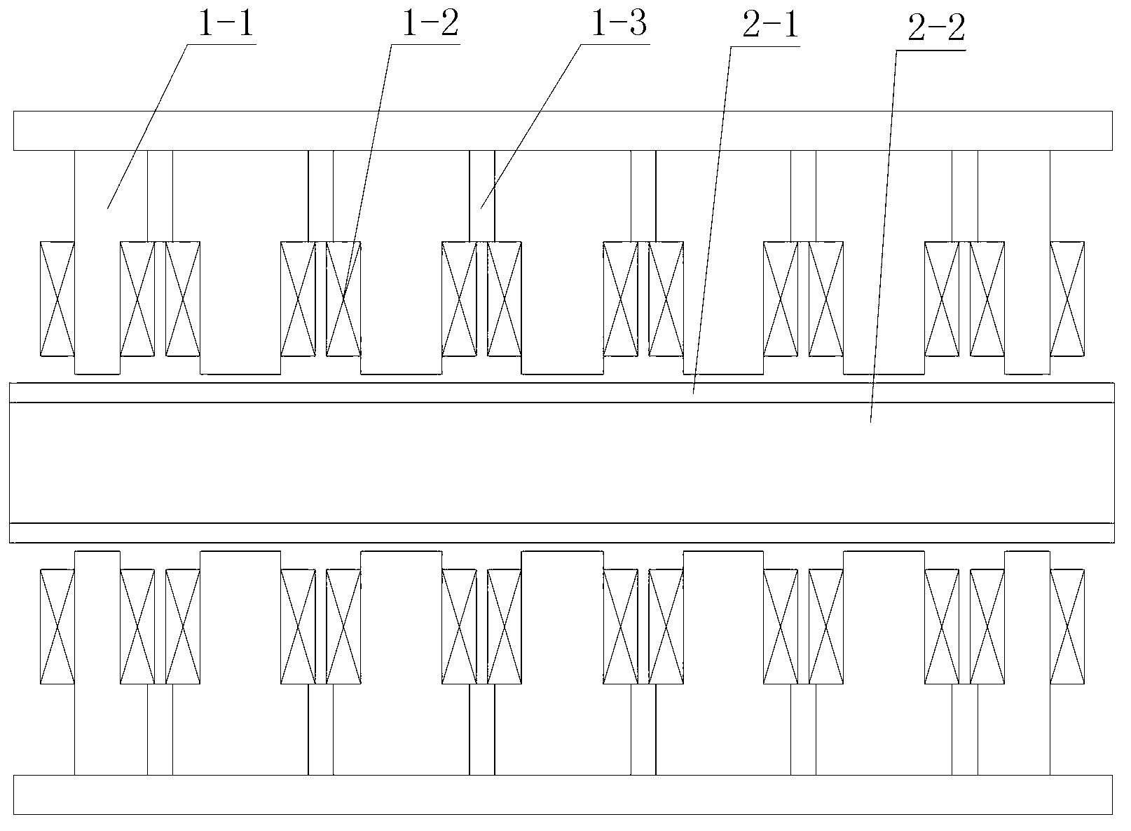
[0076] Specific implementation mode three: the following combination image 3 and Figure 4 Describe this embodiment, the linear electromagnetic damper with a series magnetic circuit structure described in this embodiment, the electromagnetic damper is a double-primary structure, the two primary mirrors are symmetrically arranged on both sides of the secondary, and the primary and secondary are air gap;

[0077] Each primary is composed of a primary iron core 1-1, an excitation winding 1-2 and 2n-1 primary permanent magnets 1-3, and the air gap side surface of the primary iron core 1-1 is evenly opened along the relative movement direction of the primary and secondary 2n-1 winding slots, so that the primary core 1-1 forms a structure in which the primary teeth and the winding slots alternate, the slotting direction of the winding slots is perpendicular to the relative movement direction of the primary and secondary, and n is a positive integer;

[0078] There is a coil wound...


PUM


Abstract

The invention relates to a linear electromagnetic damper with a serially-connected magnetic circuit structure, belongs to the technical field of motors and aims to solve the problems that prior thrust loading testing devices of linear motors can only load thrust on motors in a single direction, and loaded thrust cannot be changed continuously. The linear electromagnetic damper comprises a primary component and a secondary component, and air space is formed between the primary component and the secondary component; the primary component is composed of a primary iron core, an exciting winding and (2n-1) primary permanent magnets. (2n-1) winding grooves are evenly opened on the surface of the air space side of the primary iron core along the relative moving direction of the primary component and the secondary component, so that a primary tooth and winding groove alternating structure is formed on the primary iron core. Grooving directions of the winding grooves are perpendicular to the relative moving direction of the primary component and the secondary component. A coil is wound on each primary tooth, and coils on all the primary teeth are connected in series to form the exciting winding. A primary permanent magnet is embedded in each permanent magnet groove on the yoke portion of the primary iron core.

Description

technical field [0001] The invention relates to a linear electromagnetic damper with a series magnetic circuit structure and belongs to the technical field of motors. Background technique [0002] In the field of modern processing industry, many occasions such as laser cutting, high-speed grinding machines, precision lathes, machining centers, etc. require high-speed and high-precision linear motion, while traditional methods can only be obtained by means of intermediate links such as rotating motors and ball screws. Linear motion, which inevitably has disadvantages such as large inertia, large friction, and backlash. In recent years, with the advancement of linear motor technology, more and more occasions have begun to directly apply linear motors to obtain linear motion. Due to the direct drive technology, the linear motor has the advantages of fast speed, high acceleration, high positioning accuracy, long stroke and fast dynamic response, which just meet the requirements...

Claims


Application Information

Patent Timeline
IPC IPC(8): F16F6/00
Inventor 寇宝泉金银锡杨俊白相林
Owner HARBIN INST OF TECH
Why Eureka
Try Eureka