Pipeline pressure measuring device, energy-saving stove and energy-saving stove system
A technology for measuring device and pipeline pressure, used in measuring devices, household stoves/stoves, measuring fluid pressure, etc., can solve problems such as increased cost, insufficient combustion, blockage, etc., to avoid corrosion damage or blockage, and simple structure. Effect
- Summary
- Abstract
- Description
- Claims
- Application Information
AI Technical Summary
Problems solved by technology
Method used
Image
Examples
Embodiment 1
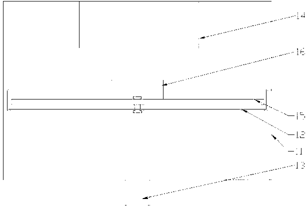
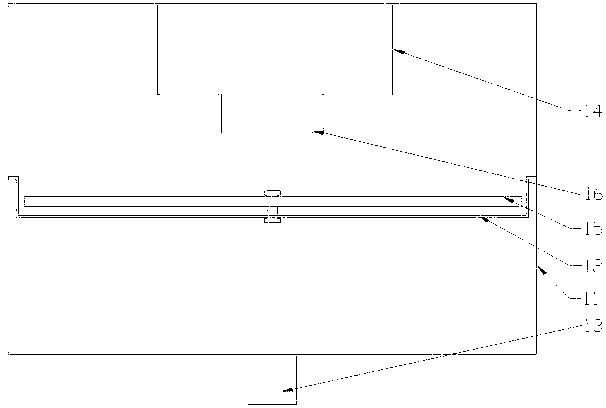
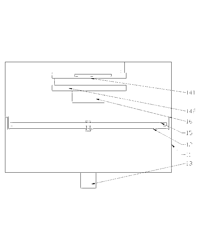
[0023] Such as figure 1 , figure 2 As shown, this embodiment is specifically a pipeline pressure measuring device. The device consists of a box body 11 . A colloidal film layer 12 is arranged inside the box body 11 . The film layer 12 divides the box body 11 into two independent spaces, one of which is provided with an inlet 13 communicating with the peripheral pipeline, and the other is provided with a pressure sensor 14 . A fixing plate 15 is fixedly arranged on a side of the film layer 12 close to the pressure sensor 14 through a connecting piece. When the inlet 13 communicates with the peripheral pipeline and a medium flows, the film layer 12 is deformed, the fixed plate 15 is pressed against the pressure sensor 14, and the pressure is transmitted to the pressure sensor 14, the pressure The sensor 14 converts the received pressure into an electronic signal and sends it to the peripheral controller 2 through wires. The fixing plate 15 is an iron plate, a steel plate, ...
Embodiment 2
[0028] Such as Figure 4 and Figure 5 As shown, this embodiment discloses an energy-saving stove. The energy-saving stove includes the pipeline pressure measuring device described in the first embodiment. It also includes a stove body 3 and a fan 4, the gas inlet passage on the stove body 3 communicates with a peripheral gas source, the air inlet passage on the stove body 3 communicates with the fan 4, and The pipeline pressure measuring device is arranged on the passage where the gas inlet channel on the stove body 3 communicates with the peripheral gas source, and the inlet 13 communicates with the passage, and a device for controlling the gas inlet is also arranged on the passage. The solenoid valve group 5 of gas volume, the fan 4 , the ignition device on the stove body 3 and the solenoid valve group 5 are all electrically connected to the controller 2 . The stove body 3 includes a furnace chamber 31, a furnace chamber 32, a metal furnace core body 33 and an air intake...
Embodiment 3
[0031] In this embodiment, an energy-saving stove system including the energy-saving stove described in Embodiment 2 is disclosed. The system also includes a main gas pipeline, and the several energy-saving stoves communicate with the main gas pipeline through the gas inlet channel on the stove body 3, and the pipeline pressure measuring device on each energy-saving stove The inlet 13 is arranged on the corresponding gas inlet channel, and the main gas pipeline communicates with the peripheral gas source.
[0032] The present invention is mainly aimed at the stove system in the kitchen. The main gas pipeline supplies gas to the working stove in the kitchen. According to the gas pressure of the corresponding stove pipeline measured in real time by the pipeline pressure measuring device on each working stove, the real-time change of the pressure in the pipeline can be obtained through the sensor output signal, so that according to the relationship between the pipeline pressure ...
PUM
 Abstract
Description
Claims
Application Information
 - R&D
- Intellectual Property
- Life Sciences
- Materials
- Tech Scout
- Unparalleled Data Quality
- Higher Quality Content
- 60% Fewer Hallucinations
Browse by: Latest US Patents, China's latest patents, Technical Efficacy Thesaurus, Application Domain, Technology Topic, Popular Technical Reports.
© 2025 PatSnap. All rights reserved.Legal|Privacy policy|Modern Slavery Act Transparency Statement|Sitemap|About US| Contact US: help@patsnap.com


