Ammonia synthesis catalyst and ammonia synthesis method

A technology for synthesis of catalysts and ammonia, applied in chemical instruments and methods, catalyst activation/preparation, physical/chemical process catalysts, etc., can solve the problems of high electronegativity of accelerators, and achieve the effect of simple manufacture and low energy consumption

Active Publication Date: 2013-08-07
TOKYO INST OF TECH +1
View PDF20 Cites 25 Cited by
  • Summary
  • Abstract
  • Description
  • Claims
  • Application Information

AI Technical Summary

Problems solved by technology

[0007] Generally, in the case of using an acidic compound such as alumina as a carrier, it is necessary to add a large amount as Accelerator compound, the accelerator has a large electronegativity

Method used


Image

  • Ammonia synthesis catalyst and ammonia synthesis method
  • Ammonia synthesis catalyst and ammonia synthesis method
  • Ammonia synthesis catalyst and ammonia synthesis method

Examples


Embodiment 1

[0085]

[0086] CaCO 3 and Al 2 o 3 The powders were mixed in such a way that the ratio of Ca to Al was 11:7, and heated in an alumina crucible at 1300°C for 6 hours. The obtained powder was inserted into a silica glass tube and placed in a 1×10 -4 Heated at 1100° C. for 15 hours in Pa vacuum. 3 g of the thus obtained powder and 0.18 g of metal Ca powder were inserted into a silica glass tube, heated at 700° C. for 15 hours to make the inside a metal Ca vapor atmosphere, and a conduction electron concentration of about 2×10 was obtained. 21 cm -3 C12A7:e - (denoted as C12A7e 21 ) powder.

[0087]

[0088] The obtained C12A7e 21 1g of powder and Ru dissolved in hexane solvent 3 (CO) 12 Mix and evaporate the solvent to dryness. At this time, according to the loading amount of Ru relative to C12A7e 21 The powder is 6wt% and the Ru in the solvent is adjusted 3 (CO) 12 amount. The catalyst precursor was formed by heating the obtained powder at 100°C under vacuum ...

Embodiment 2

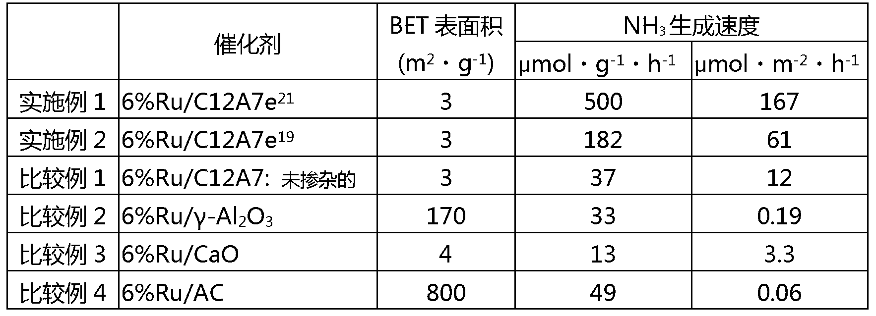
[0092] used a 1×10 19 cm -3 The chemical equivalent of electrons composed of C12A7 (C12A7e 19 ), except that, the ammonia synthesis reaction was carried out under the same conditions as in Example 1. The ammonia production rate is shown in Table 1.

Embodiment 3

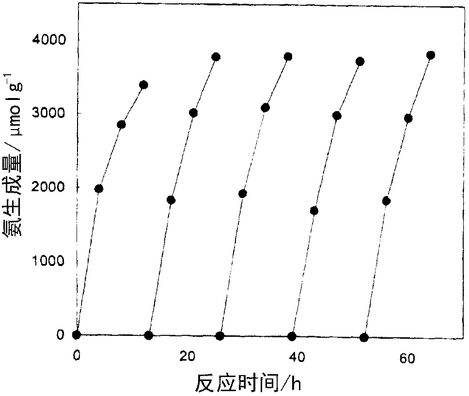
[0105] Using the same conditions as in Example 1, after carrying out the synthesis reaction for more than ten hours, the reaction system was vacuum exhausted, and then the N 2 6.7kPa and H 2 20.0kPa was introduced into the reaction system, and the synthesis reaction was carried out again at 400°C for more than ten hours. The stability of the catalyst was evaluated by further repeating this operation three times. figure 1 Given in Ru / C12A7e 21 The result obtained by repeating the synthesis reaction as a catalyst. From the left: 1st, 2nd, 3rd, 4th, and 5th. It is clear that even if the synthesis reaction is repeated five times, no decrease in the catalyst activity is observed, and the synthesis reaction proceeds under catalysis. This shows that the present catalyst does not show deterioration during the synthesis reaction and is stable even when used for a long period of time.


PUM

PropertyMeasurementUnit
particle diameteraaaaaaaaaa
specific surface areaaaaaaaaaaa

Abstract

The present invention provides a catalyst substance that is stable and performs well in the synthesis of ammonia, one of the most important chemical substances for fertilizer ingredients and the like. The catalyst substance exhibits catalytic activity under mild synthesis conditions not requiring high pressure, and is also advantageous from a resource perspective. Further provided is a method for producing the same. This catalyst comprises a supported metal catalyst having a mayenite compound, containing a conduction electron of 1015 cm-3 or more, as a carrier for the ammonia synthesis catalyst. The mayenite compound used as the carrier may take any shape, including that of powder, a porous medium, a solid sintered body, a thin-film, or a solid single crystal. Use of this catalyst makes a realization that the electron donor ability toward a transition metal can be large, and the ammonia synthesis by reacting the starting material nitrogen and hydrogen on the catalyst under low reactive pressure between 10kPa and the 30MPa level at a reactive temperature between 100 and 600 DEG C can be promoted.

Description

technical field [0001] The present invention relates to an ammonia synthesis catalyst suitable for synthesizing ammonia by reacting hydrogen and nitrogen, a method for producing the catalyst, and an ammonia synthesis method using the catalyst. Background technique [0002] Artificial fertilizers (ammonium sulfate, urea fertilizers), which are indispensable in the production of grains that support human existence, are made of ammonia. The technology of ammonia synthesis using nitrogen and hydrogen as raw materials and using iron-based catalysts was invented by Haber-Bosch (called the "Haber-Bosch process") since the 1910s About a century after the completion of industrialization, it is still an essential technology that supports human life. [0003] The Haber-Bosch method is: used in Fe 3 o 4 Contains several weight percent Al in 2 o 3 and K 2 The doubly promoted iron (doubly promoted iron) catalyst of O makes the mixed gas of nitrogen and hydrogen react directly under ...

Claims


Application Information

Patent Timeline
Patent Type & Authority Applications(China)
IPC IPC(8): B01J23/78B01J23/58C01C1/04
CPCC01C1/0411B01J23/74B01J21/04B01J35/002B01J23/32B01J23/40B01J23/24B01J37/086B01J37/16B01J37/18B01J23/462B01J23/745B01J23/75B01J35/0033B01J35/1009B01J37/0201Y02P20/52
Inventor 细野秀雄原亨和北野政明金圣雄松石聪户田喜丈横山寿治林文隆
Owner TOKYO INST OF TECH
Why Eureka
Try Eureka