Tubular oil-gas separator and oil-gas separation method

A technology of oil and gas separator and separation method, which is applied in the fields of oil and gas separation and fuel gas oil and gas separator, can solve the problems of high cost, high investment, troublesome operation and management, etc., achieves small footprint, overcomes large volume, and reduces pressure drop Effect

Active Publication Date: 2013-08-14
PETROCHINA CO LTD +2
View PDF2 Cites 4 Cited by
  • Summary
  • Abstract
  • Description
  • Claims
  • Application Information

AI Technical Summary

Problems solved by technology

[0003] Production practice has proved that the main equipment in this process system, the parallel mixed pump group 3 and the tubular heating furnace 5, have low operating efficiency and high failure rate, and it is difficult and costly to maintain the long-term normal operation of the system
The fundamental reason is that the matching equipment is unreasonable, and a scientific and reasonable configuration system has not been established. This problem exists in the use of conventional container-type oil-gas separators (such as Figure 5-1 ):
[0004] When the container-type oil-gas separator is used to separate natural gas from the oil-gas mixture and used as fuel gas for the heating furnace, due to the large volume of the container-type oil-gas separator, it has to be installed outdoors, and a heat tracing and heat preservation system needs to be installed for winter antifreeze. Cause high investment and troublesome operation and management

Method used


Image

  • Tubular oil-gas separator and oil-gas separation method
  • Tubular oil-gas separator and oil-gas separation method
  • Tubular oil-gas separator and oil-gas separation method

Examples


Embodiment Construction

[0029] In order to make the technical solution of the present invention clearer, a specific introduction will be made below in conjunction with the accompanying drawings.

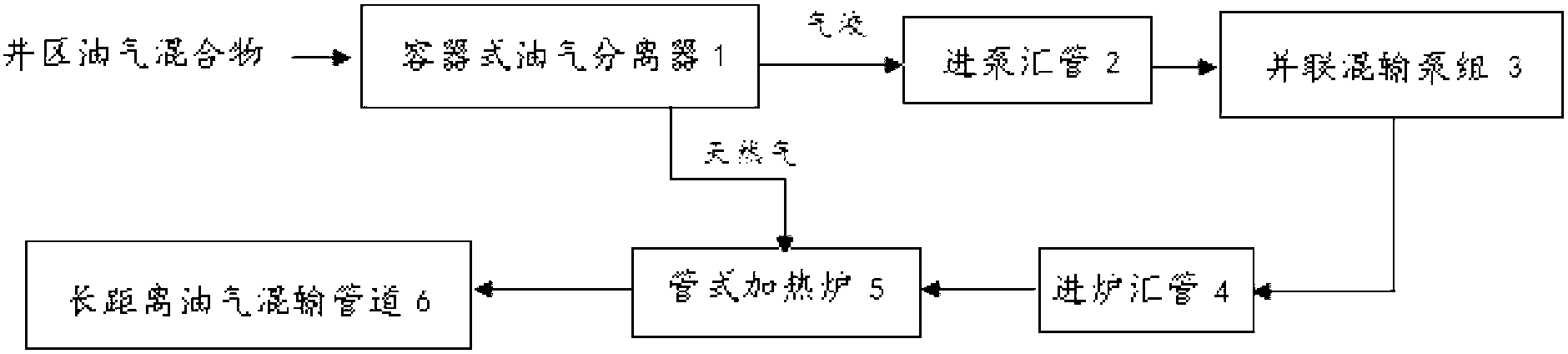
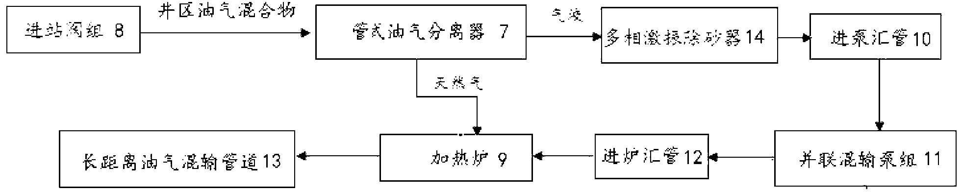
[0030] The oil-gas separator is the key supporting equipment in the oil-gas mixed transportation system, such as figure 1 In the shown oil-gas mixed transportation system, a container-type oil-gas separator 1 is used. The present invention designs a pipe-type oil-gas separator 7, which can replace the container-type oil-gas separator 1 for figure 1 The system shown can also be used for figure 2 The oil-gas mixed transportation system shown. figure 2 In the oil-gas mixed transportation system shown, the inlet end of the pipe-type oil-gas separator 7 is connected to the manifold after the inlet valve group 8 to receive the oil-gas mixture, and part of the natural gas is separated from the oil-gas mixture as the fuel for the heating furnace 9 The 7 outlet ends of the tubular oil-gas separator are divided i...


PUM

PropertyMeasurementUnit
diameteraaaaaaaaaa

Abstract

The invention relates to a tubular oil-gas separator and an oil-gas separation method. The tubular oil-gas separator is installed in an oil-gas mixing transportation system and comprises a liquid collecting tube, a gas-liquid inlet tube section and a gas-liquid outlet tube section, wherein the liquid collecting tube comprises an upper tube section and a lower tube section which are communicated with each other, one end of the gas-liquid inlet tube section is connected to a pull in valve manifold, the other end of the gas-liquid inlet tube section is connected to the inlet end of the upper tube section, the gas-liquid outlet tube section is connected to the outlet end of the lower tube section, the upper tube section is communicated with a gas-guide tube upwardly, the gas-guide tube is communicated at one end of a gas liquid removal tube, the other end of the gas liquid removal tube is communicated with a mist catcher upwardly through a pipeline, the bottom of the gas liquid removal tube is communicated with a liquid-guide tube downwardly, the liquid outlet end of the liquid-guide tube is stretched into the lower tube section, an air outlet is arranged on the upper part of the mist catcher, and a liquid discharge tube is arranged at the bottom of the mist catcher and is stretched into the bottom of the gas liquid removal tube. The invention provides the compact tubular oil-gas separator, so that the equipment volume is greatly reduced, and the separator can be installed in indoor rim space and heat tracing thermal insulation can be cancelled, the investment is reduced, and the operation and management are convenient.

Description

technical field [0001] The invention relates to a surface engineering oil and gas gathering and transportation technology in oil exploitation, in particular to a fuel gas oil and gas separator and an oil and gas separation method used in a pressurized heating oil and gas mixed transportation process system. Background technique [0002] At present, in the process of oil and gas gathering and transportation in oilfield surface engineering, more and more pressurized heating oil and gas mixed transportation technology is used. The system and process are as follows: figure 1 Shown: After the oil-gas mixture in the well area is separated by the container-type oil-gas separator 1, the gas-liquid part first passes through the inlet pump manifold 2, is transported through the parallel mixed pump group 3, and then enters the tubular heating furnace through the furnace inlet manifold 4 5 for heating, and finally enters the long-distance oil-gas mixed transportation pipeline 6; while p...

Claims


Application Information

Patent Timeline
Patent Type & Authority Applications(China)
IPC IPC(8): C10L3/10B01D45/02B01D45/04
Inventor 宋承毅杨峰
Owner PETROCHINA CO LTD
Why Eureka
Try Eureka