Fast neutron imaging method and system based on time-of-flight method

A time-of-flight and imaging system technology, applied in the direction of material analysis using radiation, can solve the problems of low detection efficiency, low spatial resolution, low signal-to-noise ratio, etc., and achieve the effect of improving detection efficiency and signal-to-noise ratio

Inactive Publication Date: 2013-08-14
CHINA INSTITUTE OF ATOMIC ENERGY
View PDF5 Cites 10 Cited by
  • Summary
  • Abstract
  • Description
  • Claims
  • Application Information

AI Technical Summary

Problems solved by technology

[0004] The purpose of the present invention is to address the defects of the prior art, to propose a fast neutron imaging method and system based on the time-of-flight method, and to solve the problems of low spatial resolution, Imaging issues with low detection efficiency and low signal-to-noise ratio

Method used


Image

  • Fast neutron imaging method and system based on time-of-flight method
  • Fast neutron imaging method and system based on time-of-flight method
  • Fast neutron imaging method and system based on time-of-flight method

Examples


Embodiment Construction

[0017] The present invention will be described in detail below in conjunction with the accompanying drawings and embodiments.

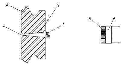
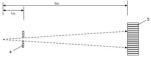
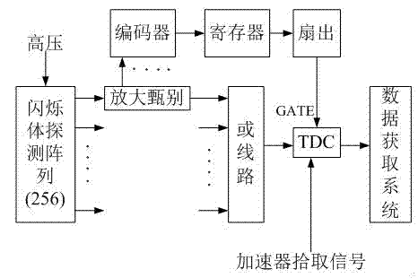
[0018] The present invention proposes to use a plurality of small scintillators to form an array detector, couple the scintillator array with a position-sensitive photomultiplier tube, place the detector at a position far from the neutron source, and place the sample at a position close to the neutron source , measure the time-of-flight spectrum of each detection unit, and then set the screening threshold to eliminate interference factors to obtain the effective counts on each detector. After the effective counts are arranged in an array, a two-dimensional image with only source neutrons working can be obtained. The purpose of effectively suppressing the background and improving the signal-to-noise ratio. At the same time, using a single scintillator as a pixel unit can improve the detection efficiency. If a 10 cm long scintillator is used to detect 1...


PUM


Abstract

The invention relates to a fast neutron imaging technology, and in particular relates to a fast neutron imaging method and system based on a time-of-flight method. The method comprises the steps that: a plurality of scintillant units form a scintillant array to enable the scintillant array to be coupled with a position sensitive detector; the whole coupled detector array is arranged away from a neutron source; a sample is arranged close to the neutron source; the measurement is performed by using the neutron time-of-flight method; interference factors are eliminated by using a conforming method to obtain effective counting on each scintillant unit detector; and the effective counting on each scintillant unit detector is arrayed to obtain a two-dimensional image in which only acting source neutrons acts. The method and the system adopt a detector array design mode, so that the detection efficiency is improved; and the time-of-flight method measurement mode can effectively remove scattered sample neutrons, an environment diffuse scattering background and a gamma background, and a signal-to-noise ratio is increased.

Description

technical field [0001] The invention relates to fast neutron imaging technology, in particular to a fast neutron imaging method and system device based on the time-of-flight method. Background technique [0002] Fast neutron imaging technology, as an important non-destructive testing technology, is an important supplementary means of x-ray imaging and thermal neutron imaging, and is currently a hot research topic in ray imaging technology. Foreign research focuses on improving the neutron source intensity and developing new imaging techniques. US Lawrence Livermore Laboratory adopts RFQ accelerator, windowless gas target, DD neutron output reaches 10 12 n / s, the opposite density exceeds 100g / cm 2 The position resolution of large objects reaches the order of millimeters. The fast neutron imaging system at Argonne can resolve water-containing defects about 0.8 mm in diameter inside a 1.25 cm thick alloy body. Fast neutron imaging methods are diversified, not only the trans...

Claims


Application Information

Patent Timeline
Patent Type & Authority Applications(China)
IPC IPC(8): G01N23/05
Inventor 鲍杰张艳萍张奇玮唐洪庆周祖英侯龙阮锡超聂阳波刘世龙王朝晖
Owner CHINA INSTITUTE OF ATOMIC ENERGY
Why Eureka
Try Eureka