Fiber grating arrays-fiber delay line based light pulse reshaper and shaping method

A fiber grating array and fiber delay line technology, which is applied in the coupling of optical waveguides, optics, instruments, etc., can solve problems such as high coupling loss, and achieve the effect of easy implementation and simple structure

Inactive Publication Date: 2013-08-14
TIANJIN UNIVERSITY OF TECHNOLOGY
View PDF4 Cites 19 Cited by
  • Summary
  • Abstract
  • Description
  • Claims
  • Application Information

AI Technical Summary

Problems solved by technology

[0004] The purpose of the present invention is to solve the problem of high coupling loss in the all-optical arbitrary waveform genera

Method used


Image

  • Fiber grating arrays-fiber delay line based light pulse reshaper and shaping method
  • Fiber grating arrays-fiber delay line based light pulse reshaper and shaping method
  • Fiber grating arrays-fiber delay line based light pulse reshaper and shaping method

Examples


Embodiment 1

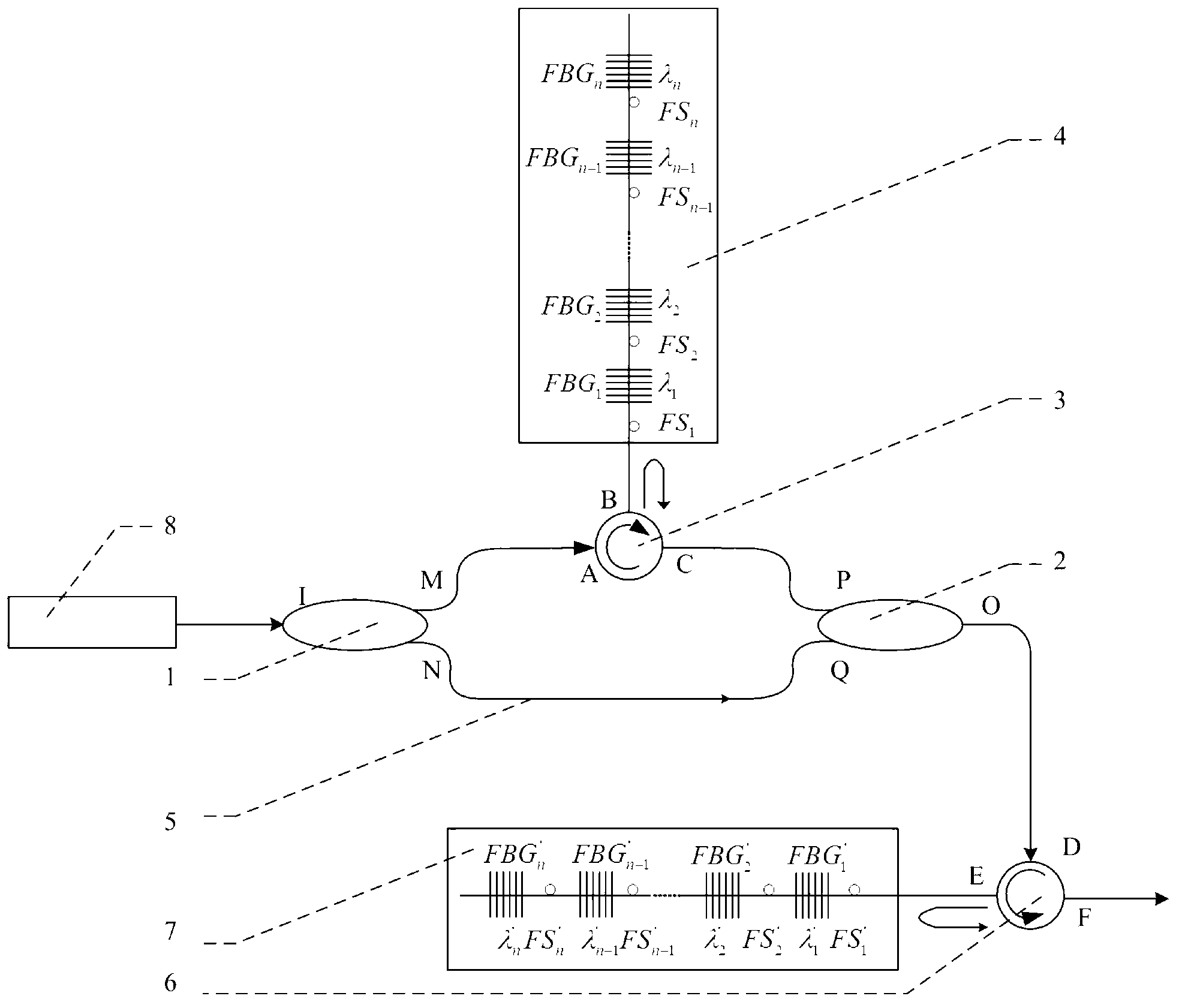
[0031] Such as figure 1Shown, a kind of optical pulse shaper based on fiber grating array and fiber delay line, it comprises: by the amplitude of the first coupler, the second coupler, the first circulator, the first fiber grating array and fiber delay line A controller, and a phase controller composed of a second circulator and a second fiber grating array; an amplitude controller, used to realize wavelength selection and adjust the amplitude of selected spectral lines; a phase controller, used to realize wavelength selection and Adjust the phase of the selected spectral line; wherein, the first port (I) of the first coupler is used to input the optical frequency comb, and the second port (N) of the first coupler is connected to the The first port (Q), the third port (M) of the first coupler is connected to the first port (A) of the first circulator, the second port (B) of the first circulator is connected to the first fiber grating array, the first The third port (C) of a c...

Embodiment 2

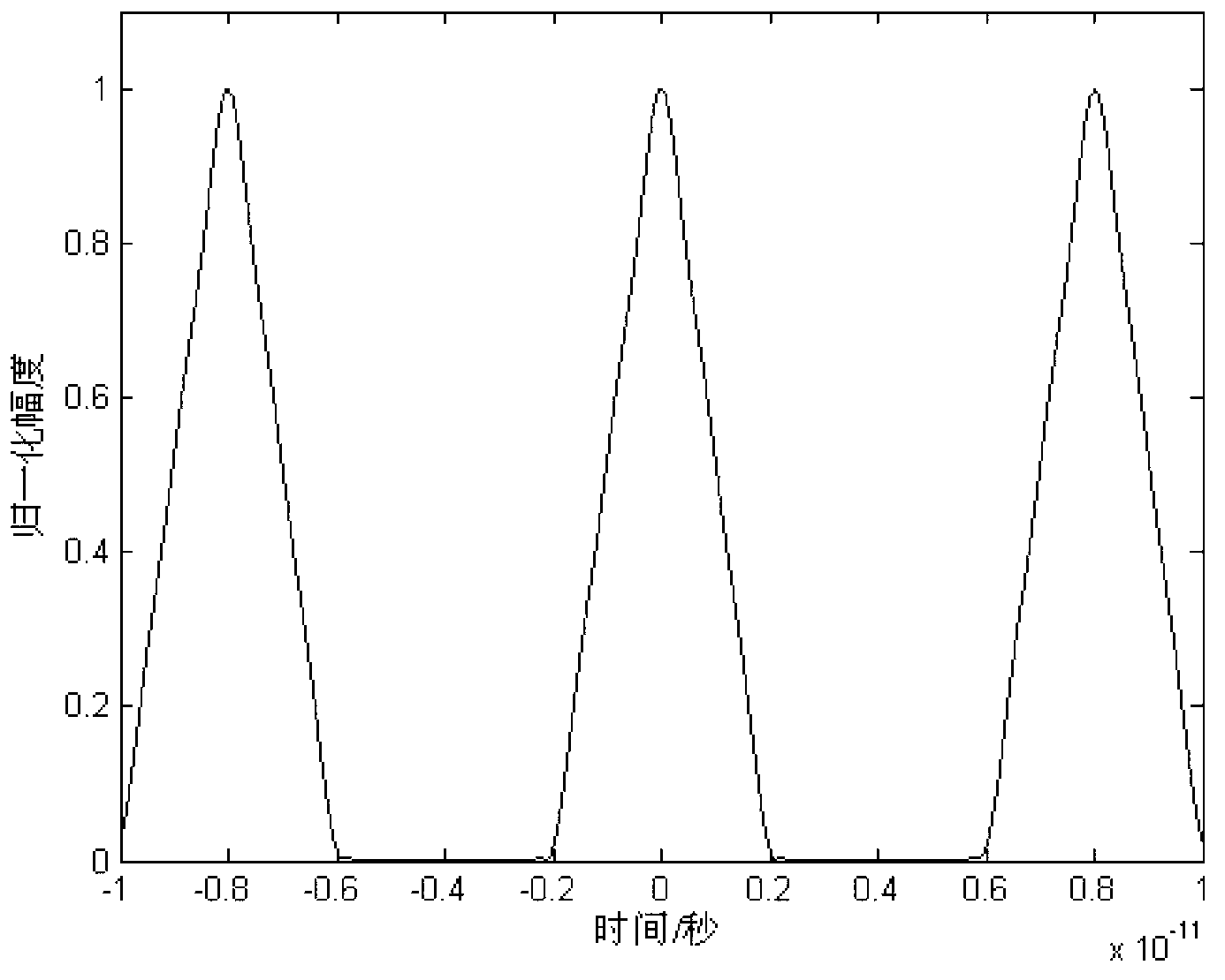
[0047] An optical pulse shaper based on a fiber grating array and a fiber delay line, the specific structure of which is similar to that of embodiment 1. Compared with Embodiment 1, the difference is that: the third port (F) of the second circulator is used to output a triangular waveform optical pulse with a repetition frequency of 125 GHz (period 8 ps) and a base width of 4 ps, and the fiber grating The array is composed of 23 groups of fiber Bragg gratings and fiber stretchers.

[0048] A kind of optical pulse shaping method based on fiber grating array and fiber delay line, this method comprises the following steps:

[0049] (1) Input the optical frequency comb through the first port (I) of the first coupler in the amplitude controller;

[0050] (2) The input optical frequency comb is shaped by the amplitude controller and the phase controller, so that the amplitude and phase of each selected spectral line are adjusted to be consistent with the amplitude spectrum and phas...

Embodiment 3

[0061] An optical pulse shaper based on a fiber grating array and a fiber delay line, the specific structure of which is similar to that of embodiment 1. Compared with Embodiment 1, the difference is that the third port (F) of the second circulator is used to output a cycle containing 4 Gaussian waveforms with different full-height half-widths, different amplitudes, and different time delays An optical pulse with a repetition frequency of 125 GHz (period 8 ps), the fiber grating array is composed of 31 groups of fiber Bragg gratings and fiber stretchers.

[0062] A kind of optical pulse shaping method based on fiber grating array and fiber delay line, this method comprises the following steps:

[0063] (1) Input the optical frequency comb through the first port (I) of the first coupler in the amplitude controller;

[0064] (2) The input optical frequency comb is shaped by the amplitude controller and the phase controller, so that the amplitude and phase of each selected spect...


PUM


Abstract

The invention discloses a fiber grating arrays- fiber delay line based light pulse reshaper and a shaping method thereof. The reshaper comprises a amplitude controller composed of a first coupler, a second coupler, a first circulator, a first fiber grating array and a fiber delay line, as well as a phase controller composed of a second circulator and a second fiber grating array, wherein the amplitude controller is used for realizing the functions of selecting wavelength and controlling spectral line amplitude; the phase controller is used for realizing functions of selecting wavelength and controlling spectral line phase; each fiber grating array is composed of an optical fiber bragg grating and a fiber tensioner; all-optical arbitrary waveform output is realized through spectrum shaping of an optical frequency comb; the adjustment for amplitude and phase position of different spectral lines of an input optical frequency comb can be realized through adjusting the fiber tensioners in the two fiber grating arrays, so as to obtain the output of light pulse in required waveforms. According to the invention, collimation control is not required, the structure is simple and the realization is easy.

Description

technical field [0001] The invention relates to an optical pulse shaper and a shaping method thereof, in particular to an optical pulse shaper based on a fiber grating array and an optical fiber delay line and a shaping method thereof. Background technique [0002] With the development of ultrafast optical technology, it has been able to generate light pulses on the time scale of picoseconds and femtoseconds, and has been widely used in ultrafast time-resolved spectroscopy, high-precision frequency measurement and other fields. However, many applications also require ultra-fast optical pulses and optical pulses of arbitrary waveforms, which has led to the rapid development of arbitrary waveform optical pulse generation technology, for pulse compression, dispersion compensation in optical fiber communications, and coherent laser control of quantum mechanical processes technologies have had a significant impact. Arbitrary waveform optical pulse generation technology is still ...

Claims


Application Information

Patent Timeline
IPC IPC(8): G02B6/28G02F1/365
Inventor 张爱玲杨孟超
Owner TIANJIN UNIVERSITY OF TECHNOLOGY
Why Eureka
Try Eureka