Fuel gas combustion device with ultra-low NOx emission amount and fuel gas distribution method

A technology of gas combustion and gas, applied in the direction of combustion methods, gas fuel burners, burners, etc., can solve the problems of increasing blower power and power consumption, combustion instability, low emission standards, etc., to achieve stable and reliable combustion , Reduce the average temperature and peak temperature, and the effect of reducing the amount of NOx

Active Publication Date: 2013-08-28
上海诺特飞博燃烧设备有限公司
View PDF5 Cites 6 Cited by
  • Summary
  • Abstract
  • Description
  • Claims
  • Application Information

AI Technical Summary

Problems solved by technology

However, this method will inevitably increase the power and power consumption of the blower. It is just to demolish the east wall to make up for the west wall. At the same time, this method also increases the instability of combustion, which is easy to cause surge and has great safety hazards.
Shanghai Nuote Feibo Combustion Equipment Co., Ltd. is an invention patent named "A Low-NOx Burner with Flue Gas Backflow Homogeneous Combustion and Its Gas Configuration Method" and the patent number is 201010582069.1. It uses a T-shaped back spray gun to partially premix gas and air , so that the gas burns evenly, and the NOx emission is less than 40ppm, but for high-power gas combustion devices, whether it can achieve lower emission standards remains to be further studied

Method used


Image

  • Fuel gas combustion device with ultra-low NOx emission amount and fuel gas distribution method
  • Fuel gas combustion device with ultra-low NOx emission amount and fuel gas distribution method
  • Fuel gas combustion device with ultra-low NOx emission amount and fuel gas distribution method

Examples


Embodiment Construction

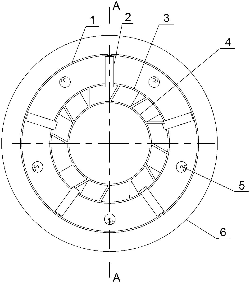
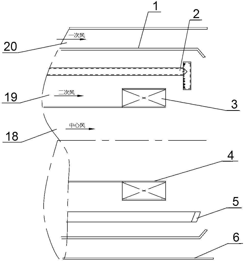
[0023] figure 1 and figure 2 It is a structural schematic diagram of an ultra-low NOx emission gas combustion device of the present invention. Figure 9 It is a schematic diagram of furnace flame arrangement when the present invention is used.

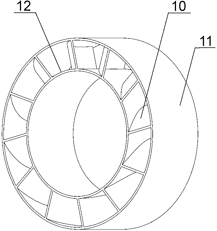
[0024] like figure 1 , 2 It can be seen that the structure of the gas combustion device includes a central cylinder 4, a swirler 3, and a throat, and is characterized in that the central cylinder 4 and the swirl are coaxially arranged in sequence outward from the central axis of the combustion device. 3, the inner throat 1 and the outer throat 6; the outer side of the upper end of the central cylinder 4 is fixedly connected with the inner ring 12 of the cyclone; the outer ring 11 of the cyclone and the inner throat 1 A plurality of T-shaped gas guns 2 and a plurality of oblique gas guns 5 are interposed, and the plurality of T-shaped gas guns 2 and the plurality of oblique gas guns 5 are staggered and evenly distributed with equal...


PUM


Abstract

The invention relates to a fuel gas combustion device with ultra-low NOx emission amount and a fuel gas distribution method, aims at enabling NOx emission amount to be smaller than 20ppm and meeting the low-emission requirement of a high-power combustor and belongs to the technical field of industrial boilers. The fuel gas combustion device with the ultra-low NOx emission amount is characterized in that a central barrel, a swirler, an inner throat and an outer throat are sequentially and coaxially arranged along the central axis of the combustion device outward, a first combustion air channel is arranged between the inner throat and the outer throat, a second combustion air channel is arranged between the inner side of the inner throat and the outer side of the central barrel, and a plurality of T-shaped fuel gas guns and a plurality of oblique-mouth fuel gas guns are arranged, staggered and evenly distributed in an equal-diameter mode. The fuel gas combustion device with the ultra-low NOx emission amount and the fuel gas distribution method have the advantages that fuel gas holes of the oblique-mouth fuel gas guns are outward, flame is formed in the first combustion air channel on the outer side of flame of the T-shaped fuel gas guns, accordingly a boiler furnace space is utilized to the most extent, the amount of produced NOx is little and is smaller than 20ppm, no CO is produced, and combustion is stable and reliable. The maximum power of one machine can reach to more than 70MW.

Description

technical field [0001] The invention relates to a gas combustion device and a gas configuration method, in particular to a gas combustion device and a gas configuration method with an ultra-low NOx emission of less than 20 ppm, and belongs to the technical field of industrial boilers. Background technique [0002] With the deepening of national energy conservation and emission reduction policies, the NOx emissions of major cities are no longer satisfied with the national standard of 100ppm. As early as 2008, Beijing and other cities have required NOx emissions to be less than 50ppm. Afterwards, Tianjin, Urumqi and some gas heating companies have The low emission requirements of high-power burners have been put forward one after another, and the gas-fired boilers in power plants are mostly required to emit less than 40ppm. However, so far in the international market, for advanced burners with NOx emissions less than 50ppm, flue gas recirculation measures are often adopted, th...

Claims


Application Information

Patent Timeline
IPC IPC(8): F23D14/02F23D14/58F23D14/70F23D14/46
Inventor 肖江东徐志斌
Owner 上海诺特飞博燃烧设备有限公司
Why Eureka
Try Eureka