Double-layer V-shaped built-in permanent magnet motor rotor for electric automobile

A technology for electric vehicles and permanent magnet motors, which is applied in the direction of electric vehicles, motors, vehicle components, etc., can solve the problems that the air-gap flux density waveform cannot achieve sinusoidal distribution, it is difficult to meet performance requirements, and the reluctance torque is limited. The effect of saliency ratio and field-weakening speed expansion ability, improvement of air-gap magnetic field waveform, and increase of reluctance torque

Inactive Publication Date: 2013-09-04
苏州和鑫电气股份有限公司
View PDF6 Cites 27 Cited by
  • Summary
  • Abstract
  • Description
  • Claims
  • Application Information

AI Technical Summary

Problems solved by technology

However, for single-layer one-shaped or V-shaped built-in permanent magnet motors, the air gap flux density waveform cannot achieve a sinusoidal distribution, so that there are 3, 5, 7, 11, 13 and other high-order harmonics in the phase-induced electromotive force, and more harmonics The wave component causes a large torque ripple, and the d-axis and q-axis reluctance of the single-layer built-in permanent magnet are not much different, the reluctance torque generated is limited, and the weak magnetic speed expansion capability, efficiency and power density are difficult Meeting the performance requirements of modern automotive drive motors

Method used


Image

  • Double-layer V-shaped built-in permanent magnet motor rotor for electric automobile
  • Double-layer V-shaped built-in permanent magnet motor rotor for electric automobile
  • Double-layer V-shaped built-in permanent magnet motor rotor for electric automobile

Examples


Embodiment 1

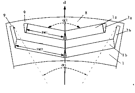
[0033] figure 2 It is a cross-sectional view of an embodiment of the double-layer V-shaped built-in permanent magnet motor rotor of the present invention. The rotor includes a rotating shaft (not shown in the figure) and a rotor core 3. The inner circumference of the rotor core 3 is evenly spaced in the radial direction. There are inner and outer double-layer permanent magnet slots 2a, 2b, and the permanent magnet slots 2a, 2b are uniformly inlaid with two rectangular strip magnets 1a, 1b, and the magnets 1a, 1b of each layer are two independent and separated magnets. Steel, two magnets form a V shape, forming inner and outer double-layer V-shaped radially magnetized rectangular strip magnets 1a, 1b, which are called double-layer V-shaped built-in permanent magnets (IPM). The permanent magnetic poles are composed of double-layer V-shaped radially magnetized rectangular strip magnets and pole shoes 8, which greatly reduces the centrifugal force caused by the rotor magnets.

...

Embodiment 2

[0037] On the basis of Embodiment 1, this embodiment optimizes the structure of the rotor.

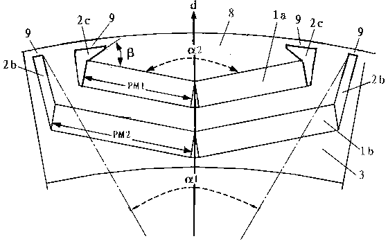
[0038] Optimizing the polar arc angle α1 of the inner V-shaped magnetic steel 1b:

[0039] By adjusting the pole arc angle α1 of the inner V-shaped magnetic steel 1b, according to the 12 poles of the motor, the angle range of the control pole arc angle α1 is: 24°-27.5°, and the others are the same as in Embodiment 1.

[0040] In this embodiment, the rotor of a 60KW motor for an electric bus is still taken as an example. The relationship between the cogging moment Tcog and the rotation angle θ of the motor rotor structure optimized in this embodiment is as follows Figure 6 As shown, the cogging moment Tcog peak value is 13Nm.

[0041] The effect of polar arc angle α1 optimization: combined with Figure 5 , Figure 6 , it can be seen that after the optimization of the polar arc angle α1, the peak value of the cogging moment Tcog is reduced from 16.5Nm before optimization (the unoptim...

Embodiment 3

[0043] On the basis of Embodiment 2, this embodiment further optimizes the structure of the rotor.

[0044] While optimizing the pole arc angle α1 of the inner V-shaped magnetic steel 1b, the included angle α2 between the outer V-shaped magnetic steel 1a is adjusted, and the range of the controlled included angle α2 is: 155°-160°. Others are identical with embodiment 2.

[0045] In this embodiment, the rotor of a 60KW motor for an electric bus is still taken as an example. The relationship between the cogging moment Tcog and the rotation angle θ of the motor rotor structure optimized in this embodiment is as follows Figure 7 As shown, the cogging moment Tcog peak value is 10.85Nm.

[0046] The optimized effect of polar arc angle α1 and included angle α2: combined Figure 5 , Figure 7 , it can be seen that after the optimization of the polar arc angle α1 and the included angle α2, the peak value of the cogging moment Tcog is reduced from 16.5Nm before optimization (initial s...


PUM


Abstract

The invention relates to a double-layer V-shaped built-in permanent magnet motor rotor for an electric automobile. Multiple groups of permanent magnet slots which are radially arranged in an inner layer and an outer layer are uniformly arranged on the iron core of the rotor at intervals along the circumferential direction; one or more V-shaped magnetized stripy magnetic steel is embedded in each permanent magnet slot. By virtue of the optimization of structures such as the angle of polar arc of inner-layer V-shaped magnetic steel, the included angle of outer-layer V-shaped magnetic steel, the width proportion of the inner-layer magnetic steel to the outer-layer V-shaped magnetic steel and the included angle of the outer-layer forcipated permanent magnet slot and the outer-layer magnetic steel, the air-gap flux density waveform is more approximate to the sinusoidal distribution, the harmonic component is reduced, the air-gap field waveform of the motor is improved, the fundamental wave frequency of spline torque fluctuation is improved, the spline fundamental wave and the ultraharmonics torque amplitude value are reduced, the torque fluctuation caused by splines is reduced, and the synthesis torque fluctuation of the motor is greatly reduced; and meanwhile, the reluctance torque is obviously increased, the salient pole rate and flux weakening speed expanding capability of the motor are improved, a constant-power speed range wider than that of a surface-mounted permanent magnet motor can be obtained, and the driving requirement of electric and hybrid automobiles can be met.

Description

technical field [0001] The invention relates to a double-layer V-shaped built-in permanent magnet motor for electric vehicles, in particular to a motor with high efficiency, high output, high power density, high reliability, high overload capacity, low fluctuation, low noise, small size, light weight and stable operation. A rotor belongs to the technical field of motors. Background technique [0002] The motor drive control system is the main executive structure in the driving process of electric vehicles, and its transmission system is the heart of electric vehicles. The three major types of electric vehicles are fuel cell vehicles (FCV), hybrid electric vehicles (HEV) and pure electric vehicles (EV). All kinds of electric vehicles use electric motors to drive the wheels. Optimizing the structure of electric motors is an important factor in improving the cost performance of various types of electric vehicles. [0003] At present, in the development of high-quality permanen...

Claims


Application Information

Patent Timeline
Patent Type & Authority Applications(China)
IPC IPC(8): H02K1/27H02K1/28H02K21/02
CPCY02T10/64
Inventor 林德芳胡岗何平
Owner 苏州和鑫电气股份有限公司
Why Eureka
Try Eureka