Robot bouncing mechanism based on hydraulic drive

A robot and hydraulic technology, applied in the field of robot bouncing mechanism, can solve the problems of low power/mass ratio of motor drive device, low energy utilization rate of robot, inability to adjust jump height, etc., so as to improve obstacle-surmounting ability and range of activities, and has a compact structure. , the effect of simple structure

Active Publication Date: 2013-09-11
NORTHWESTERN POLYTECHNICAL UNIV
View PDF7 Cites 12 Cited by
  • Summary
  • Abstract
  • Description
  • Claims
  • Application Information

AI Technical Summary

Problems solved by technology

However, the movement mode of the current robot is mainly multi-wheel drive and bionic walking or crawling. For some higher obstacles, the movement form of the above-mentioned robot is difficult to overcome or has poor obstacle-surmounting ability.
There are also some domestic robots whose bouncing mechanism is driven by a motor. A motor-driven robot bouncing mechanism is disclosed in the patent ZL201923237. The mechanism mainly drives the central cylindrical cam to rotate through the motor. The force will move down, driving the center of gravity of the mechanism to move down, and the tension spring will make the robot jump; but the robot uses a cam mechanism to increase the complexity of the control and the uncertainty of the law of motion, and the power / mass ratio of the motor drive device is small , poor load-bearing capacity
In the patent CN101058036, a locust-like jumping robot with a support mechanism in the front and a take-off mechanism in the back is disclosed, but the energy utilization rate of the robot is low, and the jump height cannot be adjusted

Method used


Image

  • Robot bouncing mechanism based on hydraulic drive
  • Robot bouncing mechanism based on hydraulic drive
  • Robot bouncing mechanism based on hydraulic drive

Examples


Embodiment Construction

[0019] This embodiment is a robot bounce mechanism based on hydraulic drive.

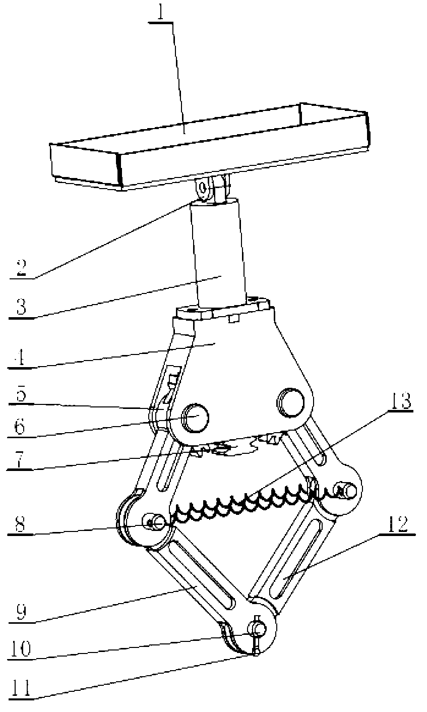
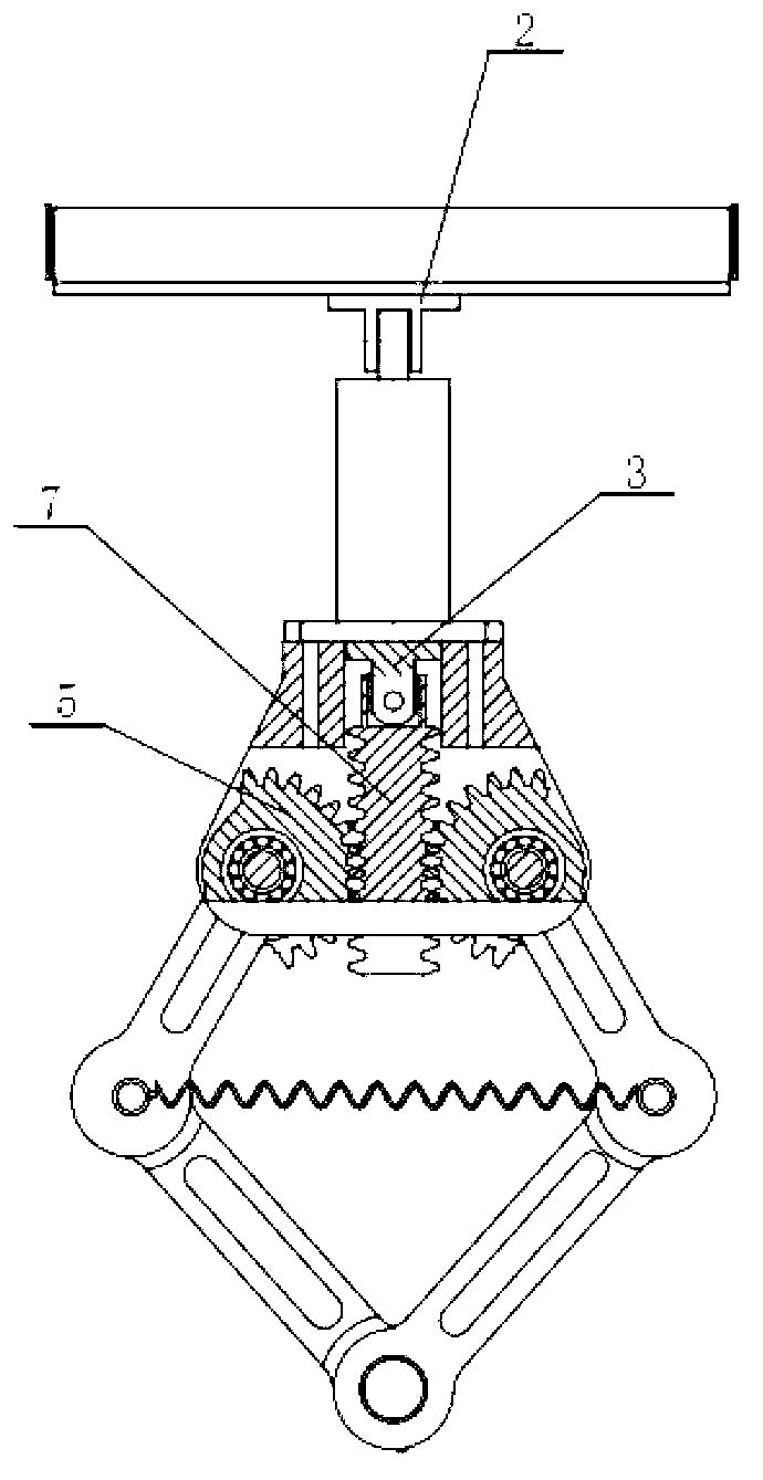
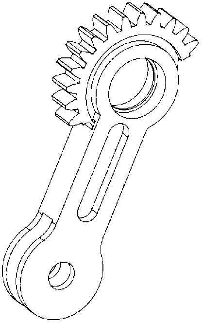
[0020] refer to figure 1 , figure 2 , the present invention is based on a hydraulically driven robot bounce mechanism, which consists of a hydraulic device 1, a hydraulic cylinder 3, a connecting seat 2, a connecting frame 4, a toothed connecting rod 5, a rotating shaft 6, a double-sided rack 7, a pin shaft 8, and a second connecting rod 9. The connecting shaft 10, the cotter pin 11, the third connecting rod 12, and the spring 13 are composed. The hydraulic device 1 is installed on the body of the robot, and the hydraulic cylinder 3 is installed under the hydraulic device 1 through the connecting seat and the lug on the top of the hydraulic cylinder. Connection, the connecting flange at the lower end of the hydraulic cylinder 3 is fixedly connected with the connecting frame 4 through bolts. The double-sided rack 7 is fixedly installed in the middle part of the connecting frame 4, and the lower en...


PUM


Abstract

The invention discloses a robot bouncing mechanism based on hydraulic drive. A hydraulic cylinder pushes a bilateral rack to drive the center of gravity of a five-rod mechanism which is composed of a belt tooth connecting rod, a second connecting rod and a third connecting rod to move downwards, an spring is stretched to store elastic potential energy at the same time, oil return of the hydraulic cylinder is controlled, the spring is released instantly to drive the whole mechanism to bounce, and the movement reliability is high. By means of the bouncing mechanism, the linear force of the spring is converted into non-linear bounce motive power, and more energy is stored under the condition of the same displacement. The bouncing mechanism takes advantage of hydraulic drive, the hydraulic cylinder is mounted on a drive joint directly, the use of a reducer is avoided, and the structure of a robot is simplified. The obstacle climbing ability and the activity range of the robot are improved notably if the bouncing mechanism is combined with a moving mode. According the bouncing mechanism, movement and power are transmitted in the mode that the rack is meshed with a gear, and thus the robot bouncing mechanism based on hydraulic drive has the advantages of being reliable in operation, long in service life, compact in structure, high in transmission precision and large in transmission power.

Description

technical field [0001] The invention belongs to the field of robots and automatic control, and in particular relates to a hydraulically driven robot bounce mechanism. Background technique [0002] At present, mobile robots are widely used, especially in environments that are more dangerous or difficult for people to reach, such as military reconnaissance, anti-terrorism activities, and exploration of alien planets; these occasions generally have complex terrain and various obstacles, requiring robots to have strong voluntary movement over obstacles. And the motion mode of current robot is mainly multi-wheel drive and bionic walking or crawling, for some higher obstacles, the motion form of above-mentioned robot is difficult to surmount or the ability to overcome obstacles is relatively poor. There are also some domestic robots whose bouncing mechanism is driven by a motor. A motor-driven robot bouncing mechanism is disclosed in the patent ZL201923237. The mechanism mainly d...

Claims


Application Information

Patent Timeline
Patent Type & Authority Applications(China)
IPC IPC(8): B62D57/02
Inventor 葛文杰谈效龙孟祥艳寇鑫徐升
Owner NORTHWESTERN POLYTECHNICAL UNIV
Why Eureka
Try Eureka