
Electromagnetic magnetron sputtering method applied to photovoltaic transparent conductive glass

A technology of transparent conductive glass and magnetron sputtering, applied in the field of electromagnetic magnetron sputtering, which can solve the problems of fragility, lower glass substrate film deposition temperature, and short discharge distance

Inactive Publication Date: 2013-09-11
JIFU NEW ENERGY TECH SHANGHAI
View PDF0 Cites 0 Cited by
  • Summary
  • Abstract
  • Description
  • Claims
  • Application Information

AI Technical Summary

Problems solved by technology

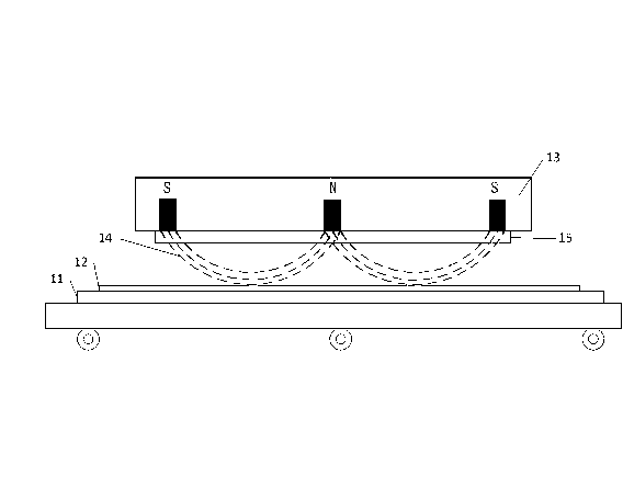
The magnetron plating method generally used in photovoltaic transparent conductive glass substrates, please refer to figure 1 As shown, it mainly first heats the glass substrate 11 to a high temperature, and then places the glass substrate under the magnetron target source. The target source 13 generates plasma 14, which is called plasma, and the plasma 14 hits the guide target 15. , so that the surface of the glass substrate 11 is coated with a layer of conductive oxide layer 12, because the glass substrate 11 has been heated to a high temperature, the conductive oxide layer 12 can be recrystallized to form a transparent conductive oxide film layer; the above-mentioned technology, although it It can make oxides form crystals, but because of the short distance of plasma discharge, the solid glass substrate needs to be as close as possible to the target source, and because the glass substrate needs to be heated at a high temperature, when heated to a high temperature of 250~300°C, then It is easy to make the glass substrate fragile and brittle; therefore, in view of the above-mentioned high temperature that makes the glass substrate fragile and brittle and the time-consuming related process method at low temperature, the inventor developed a method that can reduce the deposition temperature of the glass substrate film. At the same time, it can increase the film forming speed, an electromagnetic magnetron sputtering method applied to photovoltaic transparent conductive glass

Method used


Image

  • Electromagnetic magnetron sputtering method applied to photovoltaic transparent conductive glass
  • Electromagnetic magnetron sputtering method applied to photovoltaic transparent conductive glass
  • Electromagnetic magnetron sputtering method applied to photovoltaic transparent conductive glass

Examples


Embodiment Construction

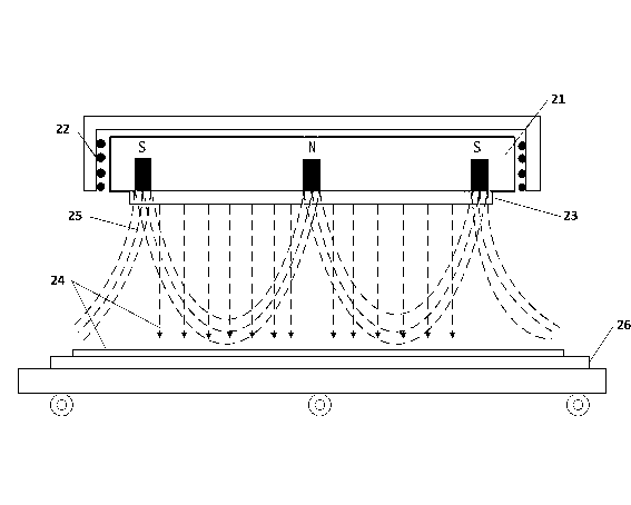
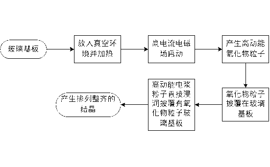
[0019] In order to make it easier to understand other features and advantages of the present invention and the effects achieved, the present invention will be described in detail as follows in conjunction with the accompanying drawings: Please refer to figure 2 , image 3 As shown, the main purpose of the present invention is to provide an electromagnetic magnetron sputtering method applied to solar transparent conductive glass, which is to put the glass substrate 26 into a vacuum environment and heat it. The heating temperature is 100 ° C ~ 150 ° C, The periphery of the target source 21 is provided with 4 sets of high-current electromagnetic fields 22 surrounding it. The 4 sets of high-current electromagnetic fields 22 are stacked on the sputtering target 23 to form an electromagnetic field 25 and generate a plasma discharge area, resulting in high kinetic energy. Oxide 24 particles, and the oxide 24 particles are deposited and coated on the glass substrate 26, the electroma...


PUM


Abstract

The invention provides an electromagnetic magnetron sputtering method applied to photovoltaic transparent conductive glass. According to the method, a glass substrate is arranged in a vacuum environment and the glass is heated, four groups of surrounding high-current electromagnetic fields are formed at the periphery of a permanent magnet of the target source, an electromagnetic field is formed to stretch a plasma discharge area, so that oxide particles with high kinetic energy are sputtered, and the oxide particles are deposited and covered on the glass substrate; the glass substrate is completely soaked in the stretched plasma area, and the oxide particles are crystallized on the glass substrate, and due to the electromagnetic field, the charged particles have kinetic energy higher than that of a general magnetic field, the amplitude of the electromagnetic field can be controlled by means of the mode of adjusting the current, the film-forming speed of the glass substrate can be increased, and a crystal structure which is neat in arrangement and combination is easily formed.

Description

Technical field [0001] The invention belongs to the field of photovoltaic glass film deposition, and in particular relates to an electromagnetic magnetron sputtering method applied to photovoltaic transparent conductive glass. Background technique [0002] The present invention is an electromagnetic magnetron sputtering method applied to solar transparent conductive glass substrates, especially one that can reduce the crystallization temperature of glass substrate films and increase the film forming speed of glass substrates. It is applied to solar transparent conductive glass substrates Electromagnetic magnetron sputtering method. Generally applied to the magnetron plating method of photovoltaic transparent conductive glass substrates, please refer to figure 1 As shown, it mainly first heats the glass substrate 11 to a high temperature, and then places the glass substrate under the magnetron target source. The target source 13 generates plasma 14, which is called plasma, a...

Claims


Application Information

Patent Timeline
IPC IPC(8): C23C14/35
Inventor 周文彬刘幼海刘吉人
Owner JIFU NEW ENERGY TECH SHANGHAI
Learn More