
Air cylinder cover and manufacturing method thereof

A technology of cylinder head and tubular parts, which is applied in the field of cylinder head and its manufacturing, can solve the problems of reducing the range of cooling water jacket of cylinder head, affecting the cooling effect of cylinder, hindering the flow of oil, etc. smooth flow effect

Active Publication Date: 2015-03-25
ANHUI JIANGHUAI AUTOMOBILE GRP CORP LTD
View PDF8 Cites 0 Cited by
  • Summary
  • Abstract
  • Description
  • Claims
  • Application Information

AI Technical Summary

Problems solved by technology

However, the first straight oil hole and the second straight oil hole are formed by machining, which requires two processes of drilling from the top of the cylinder head and drilling from the side of the air intake during the machining process. The machining accuracy of the holes is required to be high, otherwise the two holes will not be connected and the cylinder head will become a waste product, or even if they are connected, the two holes will be misaligned and connected because the axes of the two holes are not intersecting, which will prevent the oil from flowing to the rocker arm support. On the other hand, since the tool needs to be fed from the side of the air intake when drilling horizontally, and after the drilling is completed, the plugging process is added on the side of the air intake; on the other hand, due to the need to Drill holes on the air side until the first horizontal oil hole communicates with the second vertical oil hole, so there is no way to form a water jacket chamber between the oil return passage and the air intake side, because the chamber here will be blocked The second straight oil hole penetrates through to cause oil and water to mix, which reduces the reachable range of the cylinder head cooling water jacket and affects the cooling effect of the cylinder

Method used


Image

  • Air cylinder cover and manufacturing method thereof
  • Air cylinder cover and manufacturing method thereof
  • Air cylinder cover and manufacturing method thereof

Examples


Embodiment Construction

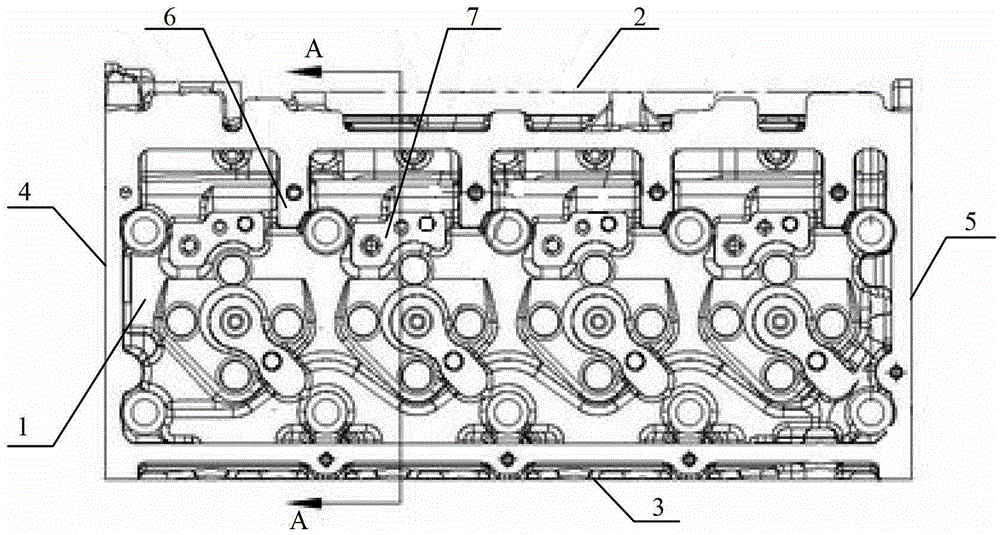
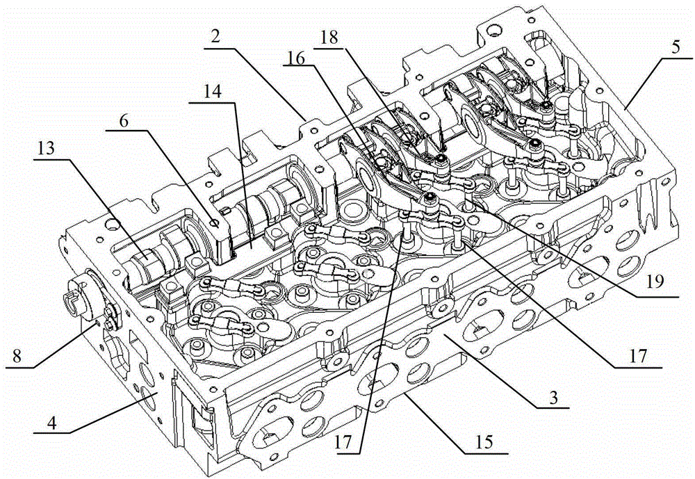
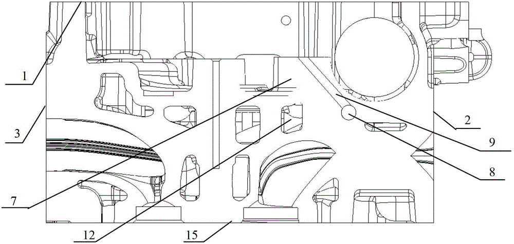
[0033] to combine figure 1 with figure 2 , the cylinder head has a top surface 1, a bottom surface 15 facing the cylinder block (not shown) and connected thereto, an intake side 2 with intake ports distributed, an exhaust side 3 with exhaust ports distributed, facing the timing train The front end face 4 and the rear end face 5 opposite to the front end face 4. Those of ordinary skill in the art should understand that the front end face 4 and the rear end face 5 are defined relative to the positions of the timing gear train, and of course other definition methods can also be used, such as exchanging the defined positions of the front and rear end faces. On the top surface 1, a camshaft mounting seat 6 is distributed, and a rocker arm support mounting boss 7 is distributed near it. The camshaft 13 is installed in the camshaft mounting seat 6, the rocker arm support 14 is installed on the rocker arm support installation boss 7, and the intake rocker arm 16 and the exhaust roc...


PUM


Abstract

The invention provides an air cylinder cover. The air cylinder cover comprises a top surface, an undersurface, an air incoming side face, an air exhaust side face, a front end face and a rear end face, camshaft mounting seats and rocker support mounting bosses are distributed on the top surface, a through oil return passage is arranged between the front end face and the rear end face, an L-shaped tubular member is cast in the air cylinder cover, an opening of the end portion of a vertical portion of the L-shaped tubular member is positioned at a position of the rocker support mounting bosses, a horizontal portion of the L-shaped tubular member is communicated with the oil return passage, and an interval is formed between the end portion of the horizontal portion and the air incoming side face. The invention further provides a manufacturing method of the air cylinder cover. The air cylinder cover has the advantages of simplicity in manufacturing and high accuracy.

Description

technical field [0001] The invention relates to the field of engines, in particular to a cylinder head in which an L-shaped tubular part is cast as a lubricating oil channel and a manufacturing method thereof. Background technique [0002] In the development process of the automobile industry, how to realize the miniaturization and compactness of the engine has always been the goal pursued by the designers. [0003] In the invention patent of Chinese patent application number: 96192117.X, application date: 1996-10-16, and the invention name "rocker arm assembly of internal combustion engine", an internal combustion engine is disclosed, and the valve rocker arm is installed to the cylinder through the rocker arm support When installing the rocker arm support on the cylinder head and fastening it to the cylinder head, it is necessary to cast a rocker arm support installation boss on the cylinder head. Moreover, in order to provide lubrication to the valve rocker arm, a lubric...

Claims


Application Information

Patent Timeline
Patent Type & Authority Patents(China)
IPC IPC(8): F02F1/24F01M11/00
Inventor 胡志胜靳素华喻春凤钱德猛徐涛郑久林
Owner ANHUI JIANGHUAI AUTOMOBILE GRP CORP LTD
Learn More