Collimator lens, optical scanning device and image forming apparatus using same

A technology of optical scanning device and collimating lens, which is applied in the fields of lens, image communication, electrical recording technology using charge pattern, etc., and can solve the problems of insufficient imaging performance and unavailability

Active Publication Date: 2013-09-11
KYOCERA DOCUMENT SOLUTIONS INC
View PDF4 Cites 5 Cited by
  • Summary
  • Abstract
  • Description
  • Claims
  • Application Information

AI Technical Summary

Problems solved by technology

Therefore, there is a problem that even if it is intended to use a relatively inexpensive material having a large linear expansion coefficient for the housing, it cannot be used due to insufficient imaging performance.

Method used


Image

  • Collimator lens, optical scanning device and image forming apparatus using same
  • Collimator lens, optical scanning device and image forming apparatus using same
  • Collimator lens, optical scanning device and image forming apparatus using same

Examples


no. 1 approach

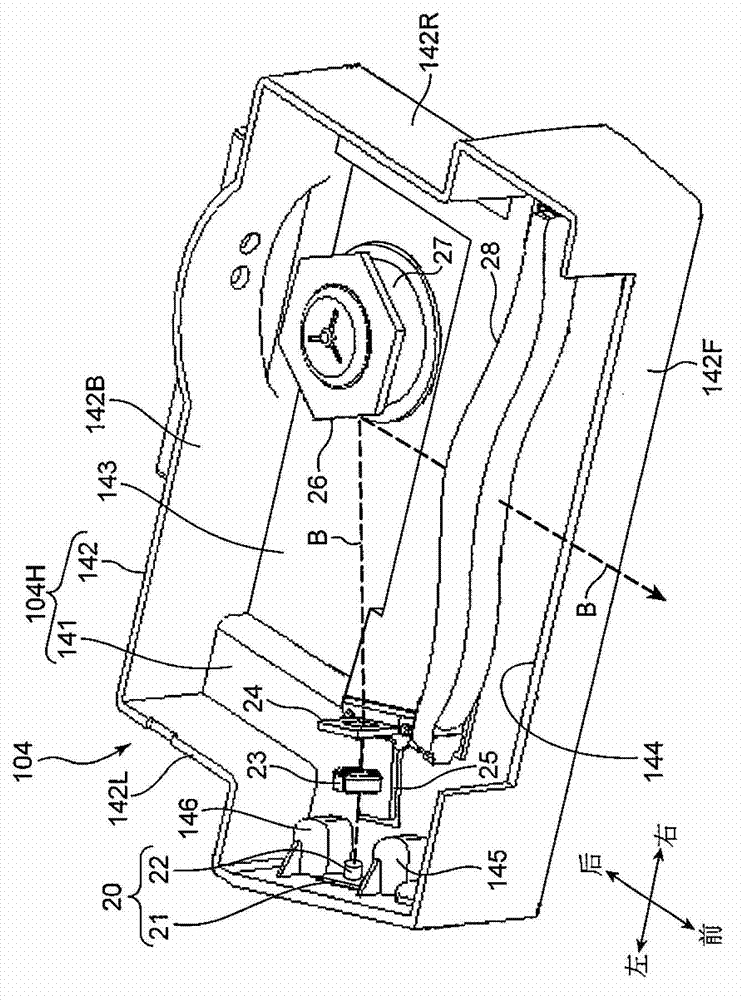
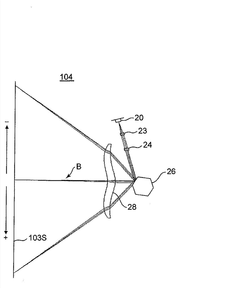
[0040] Next, the detailed structure of the optical scanning device 104 according to the first embodiment will be described. figure 2 Is a perspective view showing the internal structure of the optical scanning device 104, image 3 It is an optical path diagram showing the structure of the main scanning section of the optical scanning device 104. The optical scanning device 104 includes a housing 104H, and a laser unit 20 (light source), a collimator lens 23, a cylindrical lens 24, a polygon mirror 26 (polarizer), and an fθ lens 28 (scanning lens) contained in the housing 104H. figure 2 In the direction indicator shown, the left-right direction is the main scanning direction. The optical scanning device 104 of this embodiment is an optical scanning device in which the scanning lens is composed of only one lens (fθ lens 28).

[0041] The housing 104H includes a bottom plate 141 as a base member on which various members are placed, a side plate 142 erected substantially perpendicul...

no. 1 example

[0071] Next, an example of construction data (construction data) of the collimator lens 23 according to the first embodiment described above is shown in Table 1 as a first example. The collimating lens 23 of the first embodiment has a meniscus shape convex to the side of the polyhedral mirror 26, the first surface 231 and the second surface 232 are both aspherical surfaces, and the second surface 232 is provided with a diffraction structure. In the table, C represents the aspheric coefficient and D represents the diffraction coefficient. The optical system of the first embodiment includes the collimating lens 23 and the cover glass 20G shown in Table 1, as Figure 4 and Figure 5 Optical system as shown.

[0072] [Table 1]

[0073]

[0074] For comparison with the first embodiment, it will be as Image 6 As shown, the configuration data of the collimator lens designed to minimize the wavefront aberration when parallel light is incident from the second surface 232 is shown in Table...

no. 2 approach

[0092] Next, the optical scanning device according to the second embodiment will be described. The internal structure and optical arrangement of the optical scanning device of the second embodiment are the same as those of the optical scanning device 104 described in the first embodiment. In this second embodiment, a description will be given of an embodiment that can prevent the imaging position from shifting even if the arrangement interval between the optical members changes due to the thermal expansion of the housing 104H of the optical scanning device 104.

[0093] When the temperature of the environment in which the light scanning device 104 is installed increases, the refractive indexes of the collimator lens 23, the cylindrical lens 24, and the fθ lens 28 increase, and when the lenses are molded from a resin material, the lens shape changes due to thermal expansion. In addition, the emission wavelength of the semiconductor laser 22 becomes longer. These phenomena act to ...


PUM


Abstract

A collimator lens of the invention is provided with a first surface opposite to a light source on a light path and a second surface opposite to a polarization body on the light path; and at least one surface of the first and second surfaces is provided with a diffraction structure. In a temperature range of 0 DEG C to 60 DEG C and in a range of the emission wavelength of the light source which changes within the temperature range, divergent lights emitted from a P1 position with a distance of S1 from the second surface are shot into the second surface; under a condition of imaging on a P2 position with a distance of S2 from the first surface, and when a minimum value of a wavefront aberration of an image, which is generated at the position P2 by the divergent light emitted from the position P1 in a range of 0<=S1 / S2<=50, is WF1; and when a minimum value of a wavefront aberration of an image, which is generated at the position P2 when parallel light satisfying S1 = [infinite] enters the second face, is WF2, a relationship of WF1<WF2 is satisfied.

Description

Technical field [0001] The present invention relates to a collimator lens with a temperature compensation function, an optical scanning device using the collimator lens, and an image forming apparatus using the optical scanning device. Background technique [0002] For example, a general optical scanning device suitable for use in laser printers or copiers has optical components including: a light source that emits laser light; a polyhedron mirror that reflects the laser light and scans it by polarization; and injects the laser light into the polyhedron. The incident optical system of the mirror; and a scanning lens that images the polarized laser light on the peripheral surface (scanned surface) of the photosensitive drum. The incident optical system includes: a collimator lens (collimator lens) that transforms the divergent laser light into parallel light or convergent light; and transforms the parallel light or convergent light into linear light, and forms an image on a polygo...

Claims


Application Information

Patent Timeline
Patent Type & Authority Applications(China)
IPC IPC(8): G02B3/00G02B5/18G02B26/12G03G15/04
CPCG02B27/4283H04N1/04G02B27/30
Inventor 水谷秀次中野一成
Owner KYOCERA DOCUMENT SOLUTIONS INC
Why Eureka
Try Eureka