
Control method of buck PFC (power factor correction)

A control method and control circuit technology, applied in control/regulation systems, output power conversion devices, instruments, etc., can solve problems such as complex circuits, poor circuit conversion efficiency, and insufficient circuit efficiency, and achieve simple and easy topology. The effect of realization and practicality

Active Publication Date: 2013-09-11
MORNSUN GUANGZHOU SCI & TECH
View PDF6 Cites 7 Cited by
  • Summary
  • Abstract
  • Description
  • Claims
  • Application Information

AI Technical Summary

Problems solved by technology

For those skilled in the art, the maximum duty cycle is below 0.13, and the conversion efficiency of the circuit cannot be done well at the same cost. The computer uses the real component model, and the real component model uses the ones that can be found in the market. The best device, the simulated circuit efficiency is less than 86%
The background technology of "A Step-Down PFC Circuit" filed on July 31, 2012 with the application number 201210271808.4 analyzed the shortcomings of the BUCK topology PFC circuit in detail, and also proposed a new step-down PFC circuit, which solves the problem of too small duty cycle
The composition of the circuit is more complicated, and the circuit related to the feedback will also be more complicated

Method used


Image

  • Control method of buck PFC (power factor correction)
  • Control method of buck PFC (power factor correction)
  • Control method of buck PFC (power factor correction)

Examples


no. 1 example

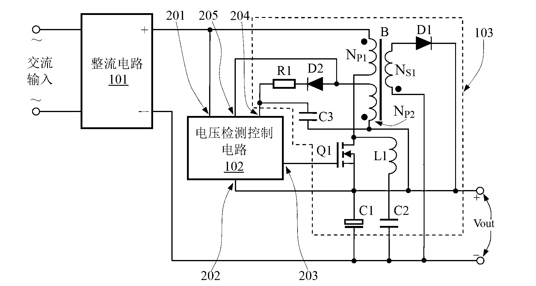
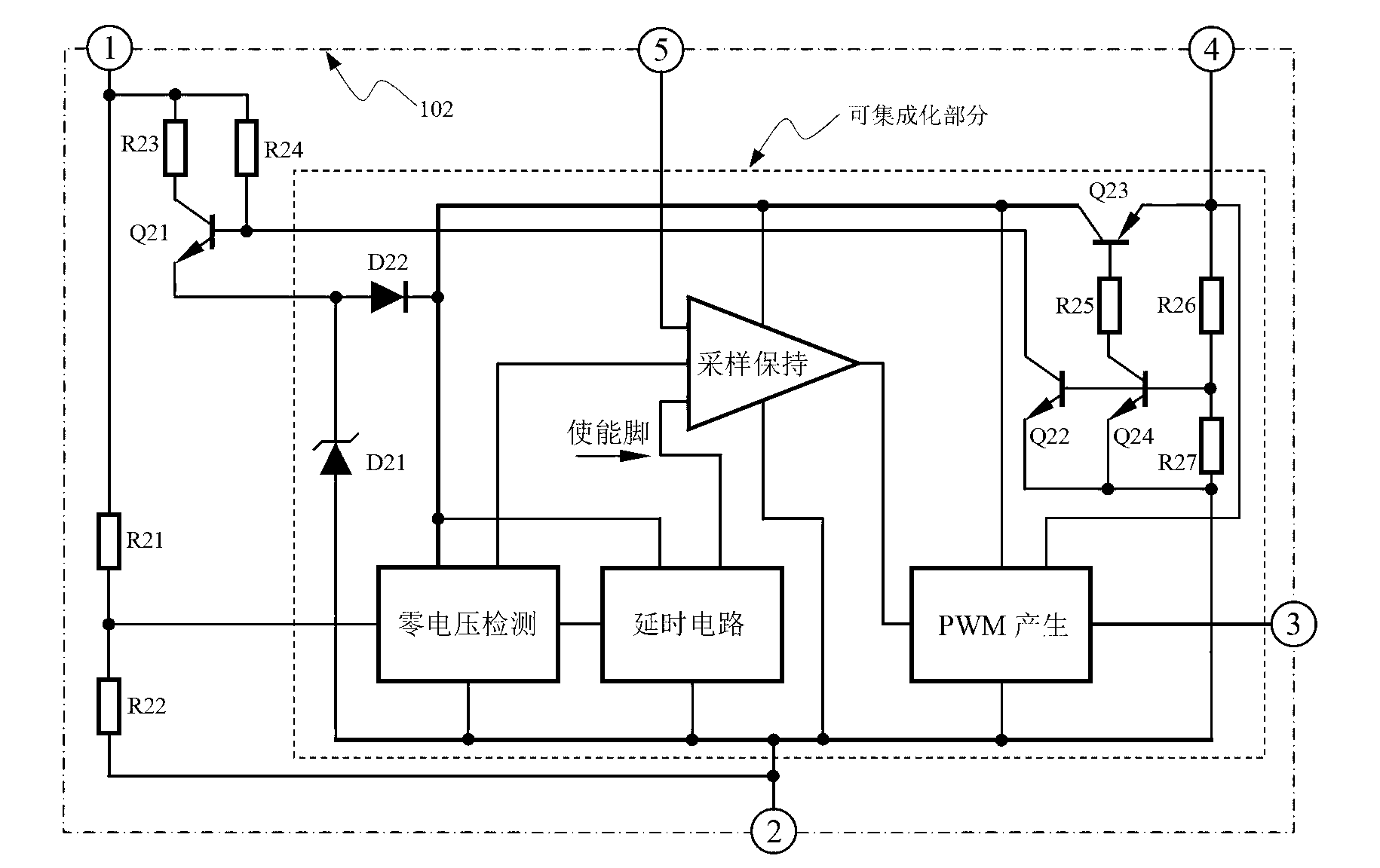
[0039] figure 1 It shows the functional block diagram of the first embodiment, following the connection relationship of the above initial technical solution, figure 1 The source of the middle N-MOS transistor Q1 is connected to the positive pole of the output terminal, that is, the positive terminal of Vout, and also includes: a rectifier circuit 101, a voltage detection control circuit 102, and a flyback circuit 103; the rectifier circuit 101 rectifies the alternating current into a pulsating direct current, and the pulsating The waveform of direct current is as figure 2 As shown, this is the waveform under 220V AC input, and its peak value is 311V. If it is 50Hz AC, then, figure 2 The T in it is 20mS, and the half-wave period of the pulsating direct current is 10mS. The voltage detection control circuit 102 has five terminals, the first terminal 201 is connected to the positive pole of the pulsating direct current; the second terminal 202 is connected to the positive pol...

no. 2 example

[0059] Figure 4 shows the second embodiment, where the first embodiment figure 1 On the basis of , a second winding Ns2 is added to the secondary side of the transformer B, and a third diode D3, a fourth diode D4, and a second inductor L2 are added to the circuit at the same time, thus obtaining Figure 4 The same name terminal of the secondary winding Ns2 of the transformer B is connected to the anode of the diode D3, the cathode of the diode D3 is connected to one end of the inductor L2, and the other end of the inductor L2 is connected to the positive pole of the output terminal Vout; the cathode of the diode D3 is simultaneously connected to the cathode of the diode D4, and the anode of the diode D4 It is connected to the opposite terminal of the secondary winding Ns2 of the transformer B, and is connected to the negative pole of the output terminal Vout at the same time. The voltage detection control circuit 102 still uses image 3 circuit.

[0060] This is a typical ...


PUM


Abstract

The invention discloses a control method of buck PFC (power factor correction). A source of an N-MOS (N-channel metal oxide semiconductor) tube in a flyback circuit is connected to a positive output of an output end. A series loop of a first inductance and a second capacitor is used as a demagnetization loop. When the N-MOS tube in the flyback circuit is on to excite a transformer, exciting current can power a load directly. When the N-MOS tube in the flyback circuit is off, the load is powered by the flyback output circuit, and a second primary side winding provides auxiliary power. During flyback, a voltage detecting control circuit 102 indirectly detects output voltage of a PFC circuit by detecting induced voltage of the second primary side winding, PWM (pulse-width modulation) duty ratio of pulse direct current at the next cycle is changed, and stable voltage output of the PFC circuit is achieved. By the control method, circuit topology is simplified, and circuits are easy to implement and practical.

Description

technical field [0001] The invention relates to an AC-DC circuit, in particular to an AC-DC converter for step-down power factor correction. Background technique [0002] Both industrial and civil use often need to change the AC voltage of various grids into DC, or even isolated DC. With the further requirements of the national standard for the power factor of electrical appliances, at present, switching power supplies with power consumption above 75W have a power factor. Requirements, that is, the working current waveform of the circuit is basically the same as the voltage waveform. [0003] At present, a power factor correction circuit has been adopted to solve this problem. The power factor correction circuit is referred to as a PFC circuit for short, which is an abbreviation of Power Factor Correction. [0004] Note: The 75W data comes from the Chinese national standard GB17625.1-1998, named "Limits of Harmonic Current from Low-Voltage Electrical and Electronic Equipmen...

Claims


Application Information

Patent Timeline
IPC IPC(8): H02M1/42H02M7/217H02M3/335
CPCY02B70/10
Inventor 王保均尹向阳
Owner MORNSUN GUANGZHOU SCI & TECH
Learn More