High frequency ultrahigh accelerating and decelerating micro-cutting motion control mechanism driven by gravity centre of linear motor

A linear motor and motion control technology, applied in the direction of drive devices, manufacturing tools, metal processing equipment, etc., can solve the problems of small continuous thrust of servo tool holders, affecting positioning and machining accuracy, affecting guide rail guiding accuracy, etc., and achieve large effective thrust , The consumption of inertial force is small, and the effect of ultra-high acceleration and deceleration cutting processing can be realized

Inactive Publication Date: 2013-09-18
JIAXING HUALING MECHATRONICS CO LTD
View PDF7 Cites 5 Cited by
  • Summary
  • Abstract
  • Description
  • Claims
  • Application Information

AI Technical Summary

Problems solved by technology

The guide rail stopper is set at the end of the guide rail, and the impact of the slide plate on the stopper affects the guiding accuracy of the guide rail, thereby reducing the machining accuracy of the tool
The protective cover set on the slide plate is in contact with the fixed body, there is line or surface friction

Method used


Image

  • High frequency ultrahigh accelerating and decelerating micro-cutting motion control mechanism driven by gravity centre of linear motor
  • High frequency ultrahigh accelerating and decelerating micro-cutting motion control mechanism driven by gravity centre of linear motor
  • High frequency ultrahigh accelerating and decelerating micro-cutting motion control mechanism driven by gravity centre of linear motor

Examples


Embodiment Construction

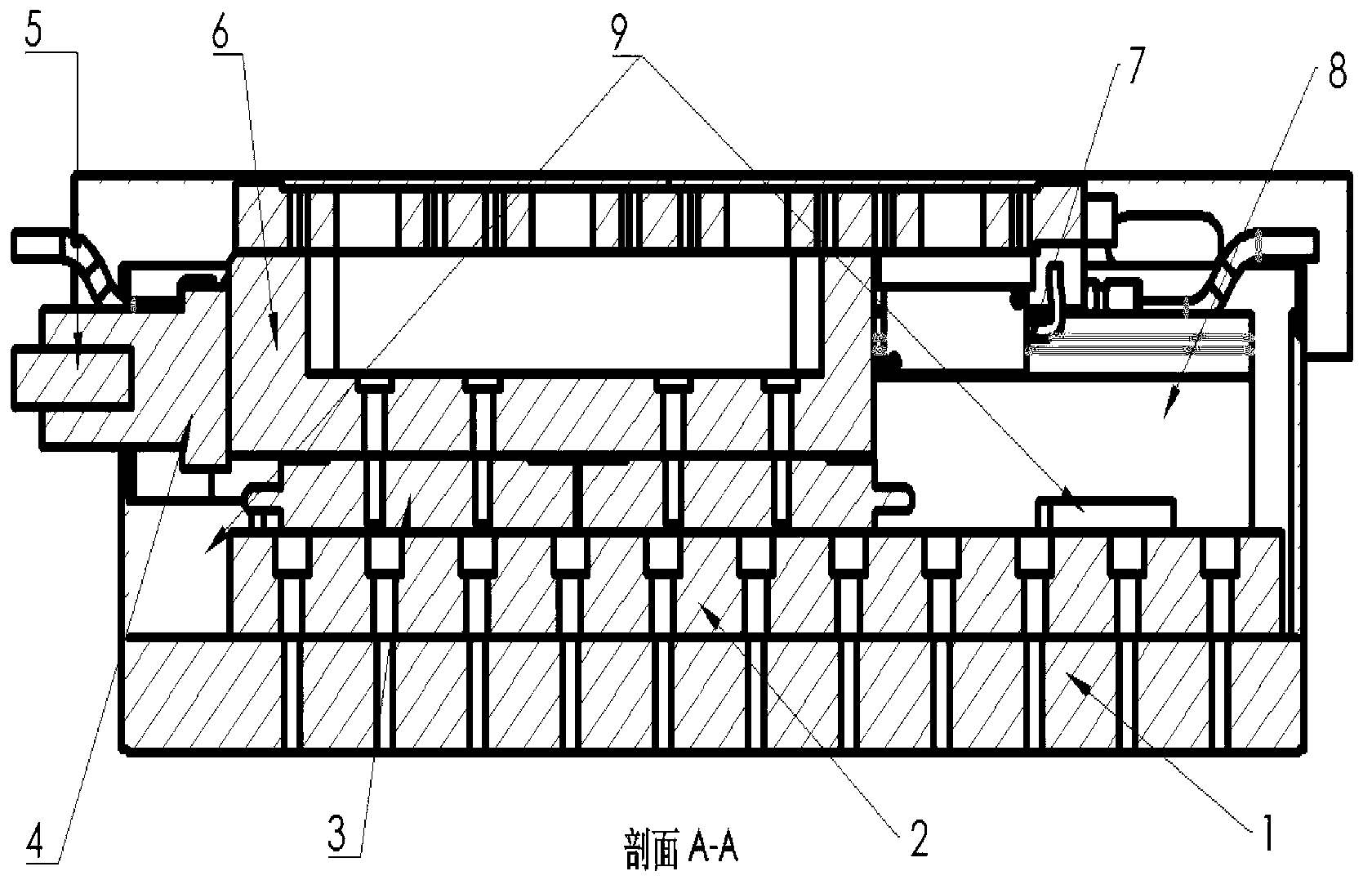
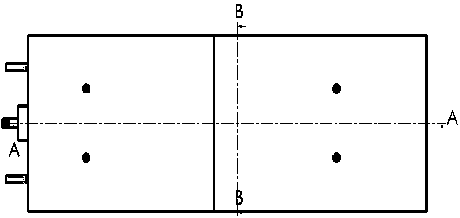
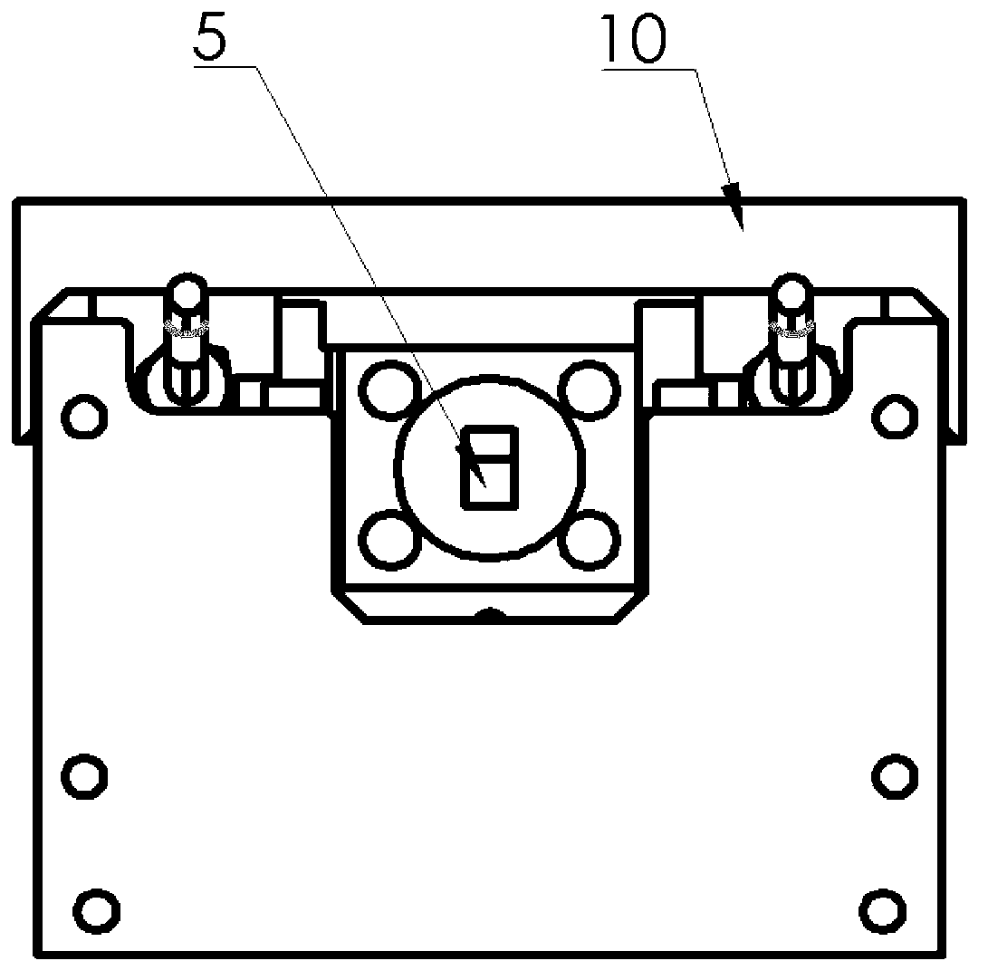
[0027] Specific embodiments of the present invention will be described below in conjunction with the accompanying drawings.

[0028] In the accompanying drawings A. The center of gravity of the left limit position of the moving part of the present invention, B. the center of gravity of the right limit position of the moving part of the present invention; C. the center of gravity of the left limit position of the traditional mechanism, D. the center of gravity of the right limit position of the traditional mechanism, E. the return left of the traditional mechanism The center of gravity of the extreme position. Surface 1 and Surface 2 are non-overlapping spatial planes, A and B are collinear on Surface 1, C is on Surface 1, D is on Surface 2, and E and C are non-overlapping spatial points.

[0029] As shown in the figure, the controller, PWM driver, position signal detection element and linear motor unit form a closed-loop servo feedback system. The position signal detection el...


PUM


Abstract

The invention discloses a high frequency ultrahigh accelerating and decelerating micro-cutting motion control mechanism driven by the gravity centre of a linear motor. A single guide rail is adopted for guiding precisely; the moving element comprises a sliding block, a linear motor runner, a workbench, a tool rest, and cutting tools which are symmetrically arranged on two sides of the guide rail, the parallel gravity centers of a plurality of linear motors drive the cutting tools; a controller, a PWM (Pulse Width Modulation) driver, a linear motor group and a position signal detecting element constitute a closed-loop servo feedback system, the digital current direct PWM is adopted by the closed-loop system to control the reciprocating running of the cutting tools, so that the positional accuracy and the linear resolution of the cutting tools can reach the level of micro-nanometer, and the reciprocating micro-cutting action of the cutting tools with high precision and resolution is realized. According to the high frequency ultrahigh accelerating and decelerating micro-cutting motion control mechanism driven by the gravity centre of the linear motor, two-level galloping protection technology is adopted, and the soft limiting and the hard limiting work together to prevent the moving element from galloping. The motion control mechanism is stable in operation, has high positioning accuracy and repeated positioning, strong ultrahigh decelerating and high-frequency responding performance, and is suitable for the technical field of ultraprecise high accelerating and decelerating high resolution micromachining.

Description

technical field [0001] The invention relates to an ultra-precision micro-cutting processing equipment, in particular to a linear motor gravity center-driven high-frequency ultra-high acceleration and deceleration micro-cutting motion control mechanism, which belongs to the technical field of ultra-precision high-acceleration and deceleration high-resolution micro-cutting processing. Background technique [0002] With the rapid development of ultra-precision machining, precision optics, microelectronics and other disciplines, people have higher and higher requirements for small-batch, high-precision, high-quality, high-efficiency ultra-precision machining technology and equipment. In the traditional CNC machining technology field, the motor drives the ball screw to realize the positioning and driving of the tool. Since the backlash of the transmission cannot be eliminated, the positioning accuracy and resolution are low. Secondly, its transmission efficiency is low, high acce...

Claims


Application Information

Patent Timeline
IPC IPC(8): B23Q5/027
Inventor 伍鹏
Owner JIAXING HUALING MECHATRONICS CO LTD
Why Eureka
Try Eureka