
Hydraulic rotary machine and method for manufacturing hydraulic rotary machine

A technology of hydraulic rotation and manufacturing methods, which is applied in the direction of liquid variable displacement machinery, mechanical equipment, machines/engines, etc., can solve problems such as longer processing time, sintering, and complex processing tracks of positioning processing tools, and achieve wear resistance and the effect of improving lubricity

Inactive Publication Date: 2017-07-04
NIHON KENKI CO LTD
View PDF3 Cites 0 Cited by
  • Summary
  • Abstract
  • Description
  • Claims
  • Application Information

AI Technical Summary

Problems solved by technology

[0010] However, in Patent Document 1, there is a problem that since the sliding surface of the cylinder bore is a smooth surface, the lubricating oil film is cut off between the cylinder bore and the piston at the high surface pressure contact point with the piston. Therefore, Wear and seizing phenomena based on solid contact between cylinder bore and piston
[0011] In addition, in Patent Document 2, there is a problem that since the copper alloy composition used for sintering the copper alloy and the cooling temperature control in the sintering process need to be strictly controlled, the manufacturing process becomes complicated, and the copper alloy material The price is high, so it will lead to a substantial increase in cost
[0012] In addition, in Patent Document 3, there is a problem that in order to process a concave shape with respect to a shape such as a cylinder bore of a cylinder block, the positioning of the workpiece and the machining trajectory of the machining tool become complicated, and therefore an expensive multi-axis Processing equipment, and the processing time will be longer
In addition, when the concave shape is worn due to sliding, similar to the case of a smooth ground surface, burning due to oil film fracture occurs.

Method used


Image

  • Hydraulic rotary machine and method for manufacturing hydraulic rotary machine
  • Hydraulic rotary machine and method for manufacturing hydraulic rotary machine
  • Hydraulic rotary machine and method for manufacturing hydraulic rotary machine

Examples


no. 1 approach

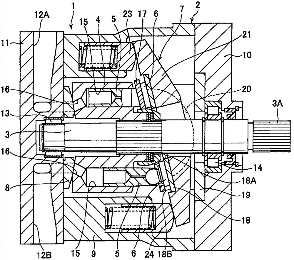
[0073] according to Figure 1 ~ Figure 4 , the first embodiment of the hydraulic rotating machine and its manufacturing method of the present invention will be described. In addition, in Figure 1 ~ Figure 4 In , the application to a variable capacity type swash plate type axial piston pump will be described as a hydraulic rotating machine.

[0074] figure 1 Among them, a variable capacity swash plate axial piston pump 1 as a hydraulic rotary machine is roughly composed of a housing 2, a rotating shaft 3, a cylinder 4, each piston 5, sliding shoes 6, a swash plate 7, and a valve plate 8, etc. .

[0075] Such as figure 1 As shown, the housing 2 is composed of a cylindrical housing main body 9 , a front housing 10 and a rear housing 11 that respectively close both ends of the housing main body 9 . Furthermore, a pair of supply and discharge passages 12A, 12B are provided on the rear cabinet 11 . These supply / discharge passages 12A, 12B are connected to piping (both shown i...

no. 2 approach

[0112] according to Figure 5 and Figure 6 , the second embodiment of the hydraulic rotating machine and its manufacturing method of the present invention will be described. In addition, in Figure 5 and Figure 6 In , the application to a variable capacity type swash plate type axial piston pump will be described as a hydraulic rotating machine.

[0113] The structure of the hydraulic rotating machine in the second embodiment is substantially the same as that of the hydraulic rotating machine in the first embodiment except for the structure of the sliding surface with the piston in the cylinder bore 45a, and a detailed description thereof will be omitted.

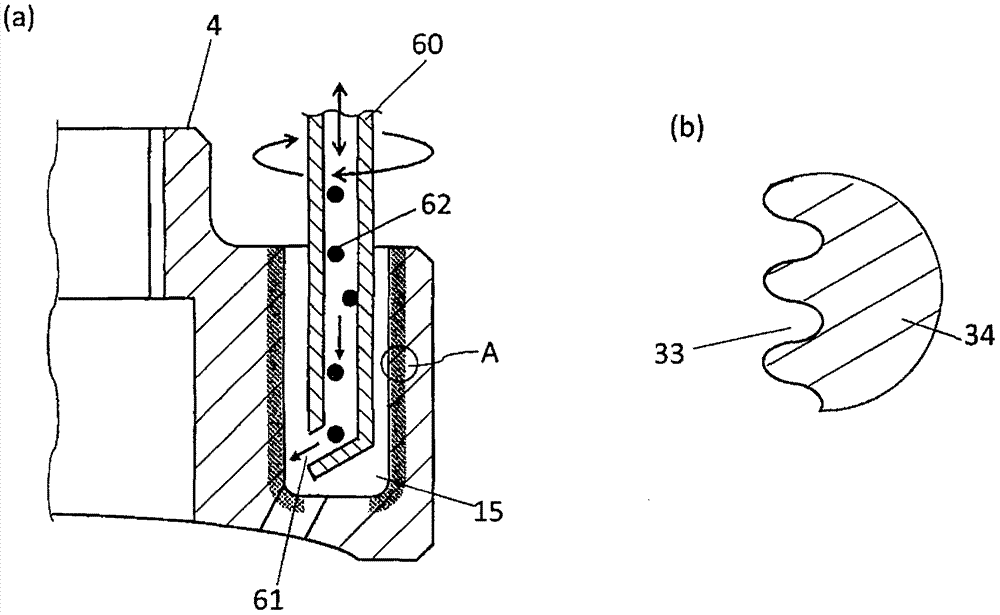
[0114] Figure 5 shows the manufacturing process of the cylinder constituting the second embodiment of the hydraulic rotating machine of the present invention, Figure 5 (a) is a longitudinal sectional view showing a part of the cylinder body in section, Figure 5 (b) is an enlarged representation Figure 5 (a) Cro...

no. 3 approach

[0136] according to Figure 9 and Figure 10 , the third embodiment of the hydraulic rotating machine and its manufacturing method of the present invention will be described. In addition, in Figure 9 and Figure 10 In , the application to a variable capacity type swash plate type axial piston pump will be described as a hydraulic rotating machine.

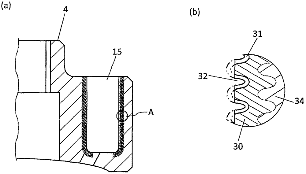
[0137] According to the first embodiment and the second embodiment of the hydraulic rotating machine and its manufacturing method according to the present invention, a nitrogen diffusion layer and a nitrogen compound layer are formed on the surface side of the cylinder bore to be the sliding surface with the piston, and the nitrogen diffusion layer The nitrogen compound layer is formed on the base material side of the cylinder hole, and the nitrogen compound layer is formed on the nitrogen diffusion layer. Then, part of the surface side of the nitrogen diffusion layer and the nitrogen compound layer is removed to form a nitroge...


PUM


Abstract

The invention provides a hydraulic rotating machine capable of improving the wearing performance and the lubricity of the sliding surface of the cylinder and the piston and a manufacturing method thereof. The hydraulic rotating machine(1) comprises a housing (2), a rotating shaft (3), a cylinder body (4), a piston (5), a slipper shoe (6), an inclined plate (7), and a valve plate (8). A cylinder hole (15) passes through the cylinder body (4), and a nitrogen diffusion layer (30) and a nitrogen compound layer (31), which are disposed in the cylinder hole (15) in the cylinder body (4), and are respectively the surface side of the sliding surface of the piston (5). The nitrogen diffusion layer (30) is disposed on a parent metal (34) side made of iron materials of the cylinder body (4), and the nitrogen compound layer (31) is disposed on the nitrogen diffusion layer (30). The parts of the surface sides of the nitrogen compound layer (31) and the nitrogen diffusion layer (30) can be removed to form the nitrogen diffusion layer (30), which can be exposed by removing the nitrogen compound layer (31), and the concave nitrogen compound layer (32), which is provided with the nitrogen compound layer in the concave part, can be provided.

Description

technical field [0001] The present invention relates to hydraulic rotary machines such as hydraulic pumps and hydraulic motors, and methods of manufacturing the same, and more particularly, to a hydraulic rotary machine relating to a cylinder bore (cylinder bore, cylinder bore) and a sliding portion of a piston in a cylinder constituting a hydraulic rotary machine. Hydraulic rotating machines and methods of manufacture thereof. Background technique [0002] Hydraulically driven machines represented by hydraulic pumps and hydraulic motors are composed of many sliding parts. Their sliding surfaces have problems such as sintering between sliding surfaces and partial abnormal wear due to the influence of breakage of the lubricating oil film due to high sliding surface pressure and instability of the sliding contact state due to fluctuations in control hydraulic pressure. risks of. Therefore, almost all sliding members constituting the sliding portion are made of steel material...

Claims


Application Information

Patent Timeline
Patent Type & Authority Patents(China)
IPC IPC(8): F04B1/22F04B53/16F04B53/14F03C1/253C21D7/06
Inventor 小林修一
Owner NIHON KENKI CO LTD
Learn More