
Muon energy and track measuring and imaging system and method

An imaging system and energy measurement technology, applied in the field of radiation imaging and radiation measurement, can solve the problem of insufficient use of muon energy information, etc., and achieve the effect of improving the performance of muon imaging technology and improving the performance of muon imaging technology.

Inactive Publication Date: 2013-09-18
TSINGHUA UNIV
View PDF8 Cites 8 Cited by
  • Summary
  • Abstract
  • Description
  • Claims
  • Application Information

AI Technical Summary

Problems solved by technology

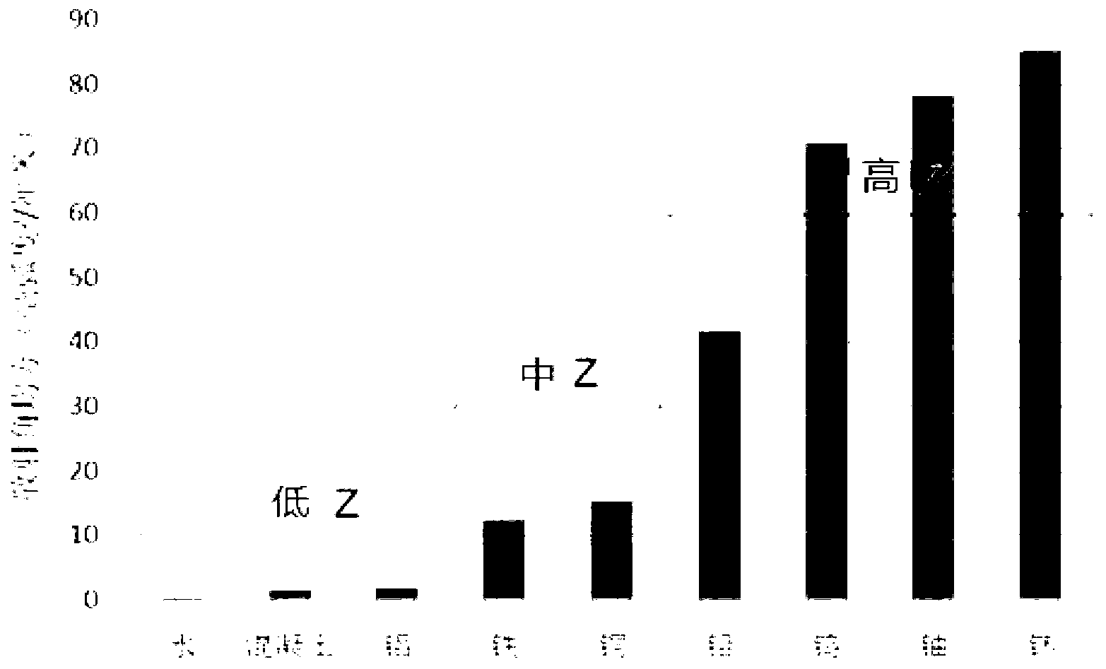
[0010] Therefore, muon imaging is mainly used in the field of detection and imaging of high-Z matter (that is, heavy nuclear materials, such as radioactive elements). The image of the object under inspection is reconstructed according to the scattering angle distribution, and the value of β in the scattering angle distribution formula used is 1, which does not make full use of the energy information of muons

Method used


Image

  • Muon energy and track measuring and imaging system and method
  • Muon energy and track measuring and imaging system and method
  • Muon energy and track measuring and imaging system and method

Examples


Embodiment Construction

[0033] Embodiments of the present invention are described in detail below, examples of which are shown in the drawings, wherein the same or similar reference numerals designate the same or similar elements or elements having the same or similar functions throughout. The embodiments described below by referring to the figures are exemplary and are intended to explain the present invention and should not be construed as limiting the present invention.

[0034] In describing the present invention, it should be understood that the terms "center", "longitudinal", "transverse", "length", "width", "thickness", "upper", "lower", "front", " Orientation indicated by rear, left, right, vertical, horizontal, top, bottom, inside, outside, clockwise, counterclockwise, etc. The positional relationship is based on the orientation or positional relationship shown in the drawings, which is only for the convenience of describing the present invention and simplifying the description, rather than ...


PUM


Abstract

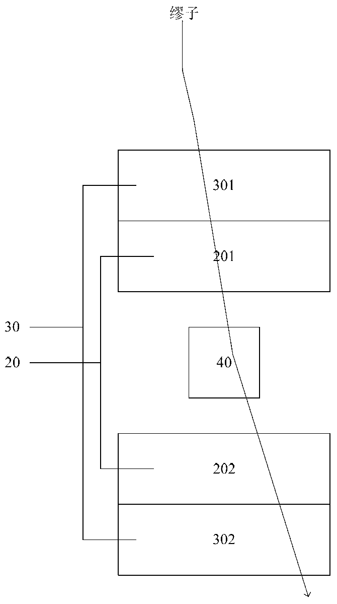
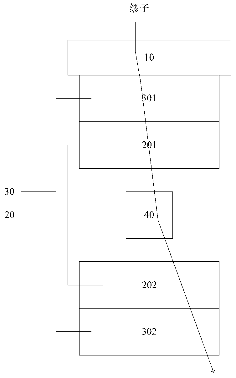
The invention discloses a muon energy and track measuring and imaging system and a method. The system comprises a detected object, a muon track measuring sub system, a muon energy measuring sub system and a muon calculating and imaging sub system, wherein natural muon in universe passes through the detected object; the muon track measuring sub system is connected with the detected object for measuring track information of muon passing through the detected object; the muon energy measuring sub system is connected with the detected object for measuring energy information of muon passing through the detected object; the muon calculating and imaging sub system is connected with the muon track measuring sub system and the muon energy measuring sub system for comprehensively utilizing the energy information and the track information of muon passing through the detected object for reconstructing an image of the detected object. The invention has the advantages of high degree of information comprehensive utilization and good imaging quality.

Description

technical field [0001] The present invention relates to the fields of radiation measurement and radiation imaging, in particular to a cosmic ray muon (abbreviated as muon, hereinafter referred to as abbreviation) energy, track measurement and imaging system and method. Background technique [0002] In 1936, Anderson and his student Niedermeier used a cloud chamber to reveal the existence of muons (muons) in cosmic rays when they used a 1cm thick platinum plate to measure the energy loss of cosmic rays. As a highly penetrating high-energy charged particle, muons can easily penetrate thick shielding layers. The rest mass is 105.7 MeV, which is about 207 times the mass of electrons. It can be either positively or negatively charged . Muons are charged particles with a mass between electrons and protons, so when muons interact with matter, μ+ is more like a light proton or a heavy positron, and μ- is more like a heavy electron. This makes its interaction with matter quite comp...

Claims


Application Information

Patent Timeline
IPC IPC(8): G01T5/00G01N23/04
Inventor 程建平王学武曾鸣曾志王义赵自然岳骞邓智罗志飞以恒冠樊星明岳晓光于百蕙
Owner TSINGHUA UNIV
Learn More