Optical film, polarizing plate, liquid crystal panel, and image display apparatus

一种光学膜、偏振片的技术,应用在光学、光学元件、偏振元件等方向,能够解决有白浊感、制造成本高、得不到表面光泽感等问题,达到降低制造成本、降低白浊感的效果

Active Publication Date: 2013-09-18
DAI NIPPON PRINTING CO LTD
View PDF7 Cites 21 Cited by
  • Summary
  • Abstract
  • Description
  • Claims
  • Application Information

AI Technical Summary

Problems solved by technology

[0004] However, such an antireflection film has the following problem: due to the difference in refractive index between the light-transmitting base material and the hard coat layer, the light reflected at the interface between the light-transmitting base material and the hard coat layer is different from the light reflected at the interface with a low refractive index. The light reflected from the interface between the layer and the hard coat layer interferes, resulting in a colored uneven pattern called interference fringes
However, the current situation is that the antireflection film has the problem of high manufacturing cost as described above.
In addition, the anti-glare film has unevenness to the extent that anti-glare properties can be obtained on the surface, so it has a cloudy feeling and does not have a glossy surface, so it is not a substitute for an anti-reflection film.

Method used


Image

  • Optical film, polarizing plate, liquid crystal panel, and image display apparatus
  • Optical film, polarizing plate, liquid crystal panel, and image display apparatus
  • Optical film, polarizing plate, liquid crystal panel, and image display apparatus

Examples


no. 1 Embodiment approach

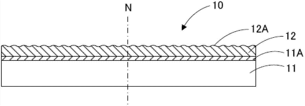
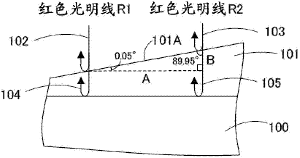
[0026] Hereinafter, the optical film according to the first embodiment of the present invention will be described with reference to the drawings. figure 1 is a schematic configuration diagram of an optical film according to this embodiment, figure 2 This is a diagram for explaining at what pitch red light rays are generated when the surface angle of the concave-convex surface is 0.05°.

[0027] "Optical Film"

[0028] Such as figure 1 As shown, the optical film 10 includes at least a translucent substrate 11 and a functional layer 12 provided on the translucent substrate 11 . Preferably near the interface of the functional layer 12 in the light-transmitting substrate 11, such as figure 1 As shown, a mixed region 11A in which components of a binder resin to be described later are mixed in the light-transmitting base material 11 and the functional layer 12 is formed. In addition, in this specification, terms such as "sheet", "film", and "plate" do not differ from each other...

no. 2 Embodiment approach

[0164] Hereinafter, the optical film according to the second embodiment of the present invention will be described with reference to the drawings. Figure 6 It is a schematic configuration diagram of the optical film according to this embodiment.

[0165] "Optical Film"

[0166] Such as Figure 6 As shown, the optical film 50 includes at least a translucent substrate 51 and a functional layer 52 provided on the translucent substrate 51 . Since the translucent base material 51 is the same substance as the translucent base material 11 described in the first embodiment, description thereof will be omitted in this embodiment. In addition, in the vicinity of the interface between the light-transmitting substrate 51 and the functional layer 52 (near the interface with the hard coat layer 53 described later), it is preferable that Figure 5 As shown, a mixed region 51A in which components of the binder resin of the translucent base material 52 and the hard coat layer 53 are mixed ...

Embodiment 1

[0272] A 60-μm-thick triacetyl cellulose resin film (manufactured by Fuji Film Co., Ltd., TD60UL) was prepared as a light-transmitting substrate, and the composition 1 for a hard coat layer was coated on one side of the triacetyl cellulose resin film to form a coating film. Next, dry air at 70° C. was circulated at a flow rate of 0.2 m / s for 15 seconds on the formed coating film, and then dried at a flow rate of 10 m / s at 70° C. for 30 seconds to make the coating film The solvent in the solvent is evaporated, and the cumulative light intensity becomes 100mJ / cm in a nitrogen atmosphere (oxygen concentration below 200ppm) 2 The coating film was cured by irradiating ultraviolet rays in the same manner as above to form a hard coat layer with a thickness of 4 μm (at the time of curing), and the optical film according to Example 1 was produced.


PUM

PropertyMeasurementUnit
visible light transmittanceaaaaaaaaaa
angleaaaaaaaaaa

Abstract

An optical film (10), a polarizing plate, a liquid crystal panel, and an image display apparatus, wherein interference fringes can be made to be invisible, and cloudiness can be reduced. In accordance with one aspect of the present invention, there is provided an optical film including a light transmissive substrate (11); and a functional layer (12) disposed on the light transmissive substrate (11), wherein the functional layer (12) has a concavo-convex surface (12A) forming a surface of the optical film (10); assuming that a slope angle of the concavo-convex surface (12A) with respect to a film plane of the optical film in a cross section along a direction normal to the film plane is a surface angle, a rate of a region in which the surface angle is 0.05 DEG or more is 50% or more in the concavo-convex surface; and the root mean square slope R delta q of a roughness curve on the concavo-convex surface is 0.003 or less.

Description

technical field [0001] The present invention relates to an optical film, a polarizer, a liquid crystal panel and an image display device. Background technique [0002] The image display surface of image display devices such as liquid crystal display (LCD), cathode ray tube display (CRT), plasma display (PDP), electroluminescent display (ELD), field emission display (FED) is usually provided with useful Anti-reflection film and anti-glare film for suppressing the reflection of external light. [0003] The antireflection film mainly includes a translucent substrate, a hard coat layer provided on the translucent substrate, and a low-refractive index layer provided on the hard coat layer. The antireflection film reduces the reflected light itself by canceling the light reflected on the surface of the low-refractive index layer and the light reflected at the interface between the low-refractive index layer and the hard coat layer. [0004] However, such an antireflection film h...

Claims


Application Information

Patent Timeline
Patent Type & Authority Applications(China)
IPC IPC(8): G02B1/10G02B5/30G02F1/1335G02B1/11G02B1/111G02B1/14G02B5/02
CPCG02B5/0221G02B5/0294G02F1/133504G02B1/10G02B5/02G02F1/1335G02B1/11
Inventor 小久见尚一郎江口淳哉古井玄皆越清馨岩田行光
Owner DAI NIPPON PRINTING CO LTD
Why Eureka
Try Eureka