A composite rotor structure bearingless switched reluctance motor

A technology of switched reluctance motor and composite rotor, which is applied to the shape/style/structure of winding conductors, electrical components, electromechanical devices, etc. High-speed performance of the motor, winding current tracking chopper control, etc., to achieve the effect of high slot full rate, simple structure, and small interphase coupling effect

Active Publication Date: 2016-08-24
NANJING UNIV OF AERONAUTICS & ASTRONAUTICS
View PDF1 Cites 3 Cited by
  • Summary
  • Abstract
  • Description
  • Claims
  • Application Information

AI Technical Summary

Problems solved by technology

[0003] Regardless of the double-winding bearingless switched reluctance motor or the single-winding bearingless switched reluctance motor, there is a strong coupling between the torque and the levitation force, and it is difficult to achieve complete decoupling of the two in the control strategy and mathematical model. It is one of the main factors that make it difficult to improve the running performance of the bearingless switched reluctance motor
In addition, due to the suspension force control, the winding current must be controlled by chopping. When running at high speed, the surge of back electromotive force makes it impossible to control the winding current by tracking and chopping, that is, the current cannot be chopped. It affects the high-speed performance of the bearingless switched reluctance motor
[0004] In order to solve the above two shortcomings of the bearingless switched reluctance motor, and based on the perspective of reducing the cost of the motor system, simplifying the control system, and improving and optimizing the performance of the suspension force, Korean scholars proposed two-phase motors with 8 / 10 and 12 / 14 structures. The bearingless switched reluctance motor is characterized in that the levitation force and torque are separately generated by the levitation winding and the torque winding respectively, the motor is a two-phase working system, and the power density of the motor is low

Method used


Image

  • A composite rotor structure bearingless switched reluctance motor
  • A composite rotor structure bearingless switched reluctance motor
  • A composite rotor structure bearingless switched reluctance motor

Examples


Embodiment Construction

[0018] Below in conjunction with accompanying drawing, the present invention is described in further detail;

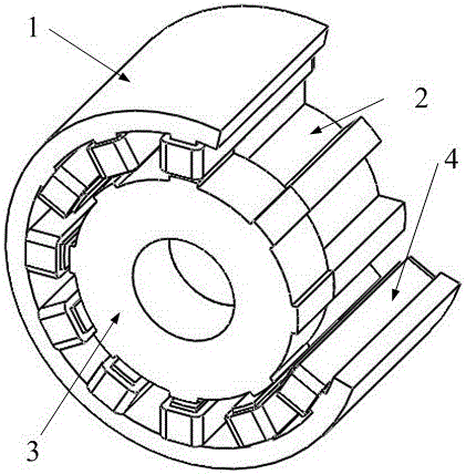
[0019] like figure 1 Shown: a bearingless switched reluctance motor with a compound rotor structure, including a stator 1, a torque rotor 2, a levitation force rotor 3, and a winding 4; a set of windings 4 are wound on the stator teeth of the stator 1; Composed of the levitation force rotor 3, the torque rotor 2 and the levitation force rotor 3 are axially superimposed and arranged in the stator 1; the torque rotor 2 is used to generate torque, and the levitation force rotor 3 is used to generate levitation force and partial torque.

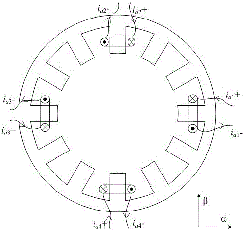
[0020] The stator is a salient pole structure with 12 teeth. Both the torque rotor 2 and the levitation force rotor 3 have 8 rotor teeth; the winding 4 is in the form of a concentrated winding, and each phase winding is composed of four windings on the stator separated by 90°, and the four windings of each phase are independently contro...


PUM


Abstract

The invention relates to a bearingless switched reluctance motor with a composite rotor structure and belongs to the field of magnetic levitation switched reluctance motors of motors, a set of windings are wound on stator teeth of a stator; rotors consist of a torque rotor and a levitation force rotor; the torque rotor and the levitation force rotor are arranged in the stator in an axial superposition manner; the torque rotor is used for generating the torque; the levitation force rotor is used for generating a levitation force and part of torque. According to the bearingless switched reluctance motor provided by the invention, only one winding is wound on the stator teeth; and compared with the traditional dual-winding bearingless switched reluctance motor, the bearingless switched reluctance motor disclosed by the invention has the advantages that the structure is simple, the coil space factor is high, copper and silicon steel sheets are saved and the manufacturing cost of a motor can be reduced. In the structure, the levitation force and the torque are decoupled, a control method is simple and the levitation performance of the motor is good. The levitation control is realized by using a smallest inductance zone; the influence of levitation current on torque current is small; and the alternate coupling action is small. In addition, the bearingless switched reluctance motor has the characteristics of high utilization rate of the winding, high power density and strong high-speed adaptability.

Description

technical field [0001] The invention relates to a bearingless switched reluctance motor with a compound rotor structure, which belongs to the field of magnetic levitation switched reluctance motors of motors. Background technique [0002] The bearingless switched reluctance motor is a new type of magnetic levitation motor developed at the end of the 20th century. The double-winding bearingless switched reluctance motor is to stack the levitation winding that generates the levitation force and the winding of the original ordinary switched reluctance motor on the stator of the motor. By controlling the current of the two sets of windings, it has the ability to rotate and self-levitate at the same time So as to realize the ultra-high speed operation of the motor. The single-winding bearingless switched reluctance motor has the ability to rotate and self-suspend at the same time by controlling the current of a set of windings. The single-winding bearingless switched reluctance...

Claims


Application Information

Patent Timeline
Patent Type & Authority Patents(China)
IPC IPC(8): H02K16/02H02N15/00H02K3/18
Inventor 刘泽远邓智泉曹鑫杨燕
Owner NANJING UNIV OF AERONAUTICS & ASTRONAUTICS
Why Eureka
Try Eureka