
Isolated soft switching dual-tube forward resonant dc/dc circuit

A dual-tube forward excitation and soft-switching technology, which is used in high-efficiency power electronic conversion, conversion equipment with intermediate conversion to AC, climate sustainability, etc. problems, to achieve the effect of reducing overlap time, reducing power loss and improving service life

Active Publication Date: 2016-04-20
ZHEJIANG UNIV
View PDF5 Cites 3 Cited by
  • Summary
  • Abstract
  • Description
  • Claims
  • Application Information

AI Technical Summary

Problems solved by technology

The dual-transistor forward DC / DC conversion circuit has disadvantages: because the power electronic device is not an ideal switch, there is a turn-on delay and a turn-off delay, which causes the switch tube Q 1 and Q 2 Overlap time between the voltages across the terminals and the current through them, causing switching losses

Method used


Image

  • Isolated soft switching dual-tube forward resonant dc/dc circuit
  • Isolated soft switching dual-tube forward resonant dc/dc circuit
  • Isolated soft switching dual-tube forward resonant dc/dc circuit

Examples


Embodiment 1

[0030] A single-phase isolated soft-switching double-transistor forward resonant DC / DC circuit, its circuit structure is as follows figure 2 shown.

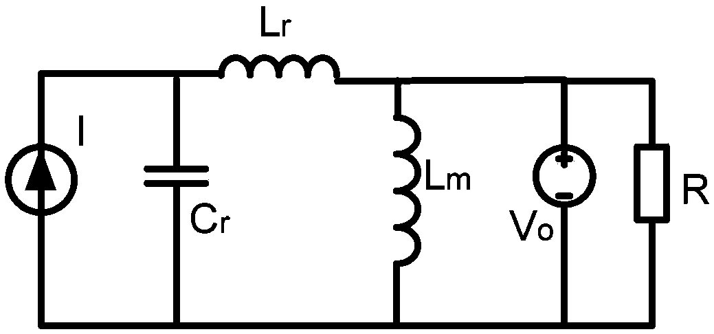
[0031] See attached figure 2 . A single-phase isolated soft-switching double-tube forward resonant DC / DC circuit, the power supply V in and the input inductance L in Composition of constant current output; switching tube Q 1 , Q 2 , the clamping diode D p1 、D p2 , high frequency isolation transformer T 1 Primary winding N P Form a dual-tube forward converter; resonant inductance L r and resonant capacitor C r Form a parallel resonant circuit; output rectifier diode D 1 , the output filter capacitor C o Form the output rectification filter circuit.

[0032] The specific connection method is: power supply V in The positive pole is connected to the input side inductor L in The input terminal, the input side inductance L in The output terminal is connected to the resonant capacitor C r input, resonant capacitor C ...

Embodiment 2

[0035] A two-phase isolated soft-switching double-transistor forward resonant DC / DC circuit, its circuit structure is as follows Figure 8 shown.

[0036] The circuit structure of the dual-transistor forward resonant DC / DC circuit can be extended to a DC / DC converter circuit structure in which multiple units are connected in parallel. It is illustrated by a double-tube forward resonant DC / DC circuit connected in parallel with two phases: the power supply V in The positive pole is connected to the input side inductor L in input, input side inductance L in The output terminal is connected to the parallel resonant capacitor C r input, parallel resonant capacitor C r The output is connected to the power supply V in The negative pole forms a loop;

[0037] Input side inductance L in The output terminal is connected to the switch tube Q 2 One end, switch tube Q 2 The other end is connected to the high frequency isolation transformer T 1 Primary winding N p1 The resonant i...


PUM


Abstract

The invention relates to electric-power, electron and electric-energy circuits, aim to provide an isolated soft switching two-diode forward resonant DC / DC (direct-current / direct-current) circuit. The circuit comprises a power source, two switching diodes, two clamping diodes, a high-frequency isolation transformer, a primary winding, a secondary winding, an output rectifier diode and an output filter capacitor, and further comprises an input side inductor, a resonant inductor and a resonant capacitor. The resonant capacitor Cr is connected with the power source in parallel, and the input side inductor is located between the resonant capacitor and the power source. The resonant inductor is connected with the transformer primary winding in series. Load formed by the resonant inductor, the resonant capacitor and the output voltage forms resonant circuits in series. By the isolated soft switching two-diode forward resonant DC / DC circuit, a power switching diode operates while zero voltage switches on and quasi-zero current is in switched off state, voltage at two ends of the power switching diode is reduced, overlap time of current passing through the power switching diode is reduced, and switching consumption of the power switching diode is reduced; energy on parasitic inductors or capacitors can be recovered, and energy converting efficiency is improved; energy consumption on the circuit is reduced, and energy is saved.

Description

technical field [0001] The invention relates to a power electronic electric energy conversion circuit, in particular to an isolated soft switch double-tube forward resonance DC / DC circuit. Background technique [0002] The forward topology has been widely used due to its simple circuit structure, electrical isolation of input and output, wide range of voltage rise and fall, easy multi-channel output, and suitable for small and medium power power conversion occasions. The dual-tube forward DC / DC converter circuit is a DC voltage conversion circuit in the forward topology in power electronics technology. Nowadays, the dual-tube forward DC / DC converter circuit generally adopts the following figure 1 The structure shown is realized: including a diode D that acts as a magnetic reset p1 and D p2 , switch tube Q 1 and Q 2 , Transformer T that isolates input and output and performs voltage step-down 1 , Diode D that limits current flow 1 , Freewheeling diode D 2 And the indu...

Claims


Application Information

Patent Timeline
Patent Type & Authority Patents(China)
IPC IPC(8): H02M3/28
CPCY02B70/10
Inventor 吴新科王夏炜
Owner ZHEJIANG UNIV
Learn More