Small two-stage light-gas gun
A light gas gun, small-scale technology, applied in the direction of weapon types, compressed air guns, weapons without explosives, etc., can solve the problems of unable to increase the projectile launch speed, occupy a large space, pollute the environment, etc., to improve safety and environmental protection, Small footprint and simple operation
- Summary
- Abstract
- Description
- Claims
- Application Information
AI Technical Summary
Problems solved by technology
Method used
Image
Examples
specific Embodiment approach 1
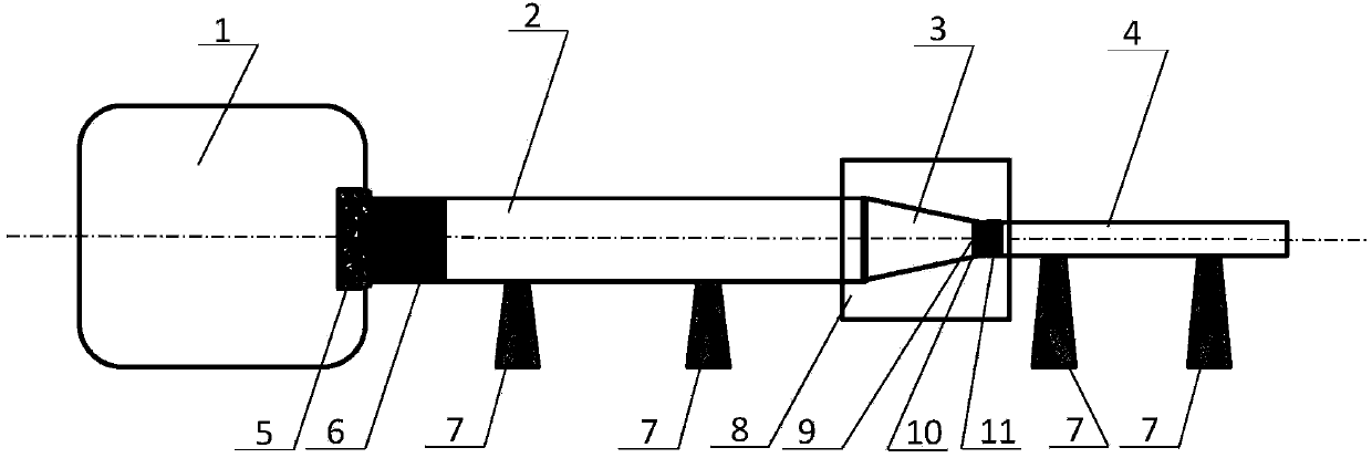
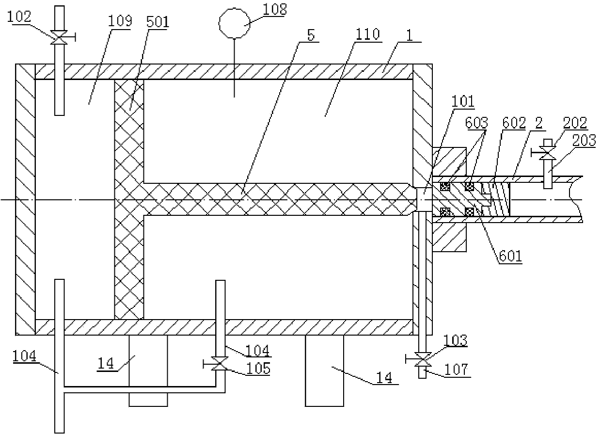
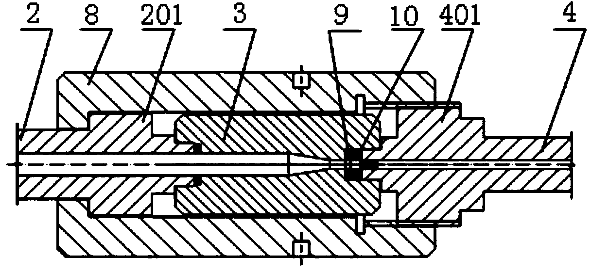
[0014] Specific implementation mode one: combine Figure 1-Figure 6 Describe this embodiment, a small two-stage light gas gun in this embodiment includes a cylinder 1, a pressure guiding tube 2, a stamping column 3, a launch tube 4, a piston handle 5, a diaphragm 9, a support 14 and a plurality of supports Seat 7, the cylinder barrel 1 is a cylinder barrel with both ends closed, the middle part of one end of the cylinder barrel 1 is provided with an air guide hole 101, a piston handle 5 is installed in the cylinder barrel 1, and the piston 501 on the piston handle 5 and the cylinder barrel The inner circumferential surface of 1 is in sliding contact, the end of the piston handle 5 points to the air guide hole 101 and the two are coaxially arranged, and the piston 501 divides the cylinder 1 into a balance chamber 109 and an air chamber 110;
[0015] The light gas gun also includes a pressure guiding body 6, a membrane breaker 10, a first sealing ring 12 and a metal sealing ring...
specific Embodiment approach 2
[0022] Specific implementation mode two: combination Figure 1-Figure 6 Describe this embodiment, the outer wall of the metal cylinder 601 of this embodiment and the inner wall of the pressure guiding tube 2 are sealed by the rubber sealing ring set on the metal cylinder 601; Membrane breaker 10 is sealed. Membrane breaker 10 is sealed and connected to launch tube 4 through a rubber sealing ring installed on membrane breaker 10. Pressure guide tube 2 is sealed and connected to punching column 3 through a rubber sealing ring installed on punching column 3. . Such setting ensures a good seal during the process of compressing hydrogen, effectively ensuring the high-speed launch of projectiles under high pressure or ultra-high pressure. This embodiment solves the problem of effective conversion of high-pressure gas driving energy. Or helium, controlled by multiple factors such as piston, stamping column and diaphragm. Due to the limitation of the allowable pressure of the high-p...
specific Embodiment approach 3
[0023] Specific implementation mode three: combination Figure 4 The present embodiment will be described. The cross sections of the first seal ring 12 and the metal seal ring 13 in this embodiment are both circular. Such an arrangement effectively ensures that the pressure guide body compresses the hydrogen until the membrane ruptures without hydrogen leakage. Others are the same as in the first or second embodiment.
PUM
 Abstract
Description
Claims
Application Information
 - R&D
- Intellectual Property
- Life Sciences
- Materials
- Tech Scout
- Unparalleled Data Quality
- Higher Quality Content
- 60% Fewer Hallucinations
Browse by: Latest US Patents, China's latest patents, Technical Efficacy Thesaurus, Application Domain, Technology Topic, Popular Technical Reports.
© 2025 PatSnap. All rights reserved.Legal|Privacy policy|Modern Slavery Act Transparency Statement|Sitemap|About US| Contact US: help@patsnap.com


