Wind driven generator coupler slipping torque calibration test bed and calibration method

A technology for wind turbines and couplings, which is used in machine gear/transmission mechanism testing, instruments, torque measurement, etc., can solve problems such as large slip torque calibration error, lag in test judgment, and complex mechanism, and achieve good application. Value, easy adjustment, good human-computer interaction

Inactive Publication Date: 2013-09-25
CHONGQING UNIVERSITY OF SCIENCE AND TECHNOLOGY +1
View PDF7 Cites 29 Cited by
  • Summary
  • Abstract
  • Description
  • Claims
  • Application Information

AI Technical Summary

Problems solved by technology

The existing problems of the currently used wind turbine coupling slip torque calibration test bench and calibration method are: 1. Driven by a linear hydraulic cylinder, the rear end of the cylinder is hinged to the base, the piston rod of the cylinder is hinged to the swing block, and the swing block is fixed on the The input end of the generator coupling, so that the reciprocating linear motion of the piston rod of the oil cylinder is changed into the reciprocating swing of the coupling. The disadvantage of this method is that the mechanism is relatively complicated, which is inconsistent with the actual driving state of the wind turbine coupling. During the test, the vibration is very large; 2. The torque detection device at the output end of the wind turbine coupling adopts a large torque sensor, and the price is relatively high; 3. During the test, the torque limiter is judged to be slipping by drawing a line on the torque limiter and observing whether it is misplaced , which will cause a delay in the test judgment and a large error in the calibration of the slip torque

Method used


Image

  • Wind driven generator coupler slipping torque calibration test bed and calibration method
  • Wind driven generator coupler slipping torque calibration test bed and calibration method
  • Wind driven generator coupler slipping torque calibration test bed and calibration method

Examples


Embodiment Construction

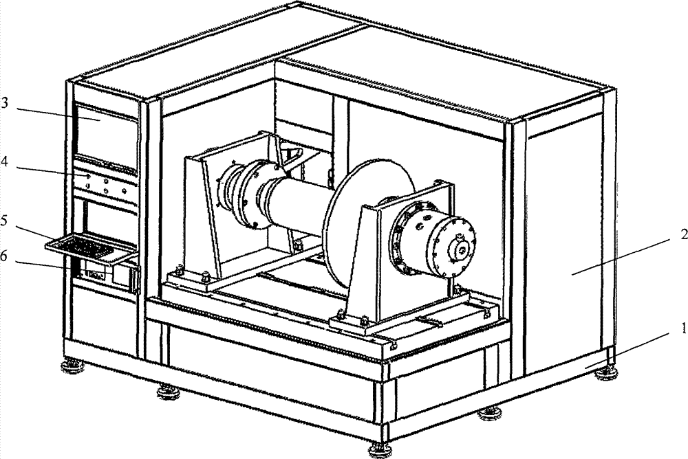
[0022] The wind turbine coupling slip torque calibration test bench of the present invention is mainly composed of a bench, a base plate, a torque loading mechanism, a torque output detection mechanism, a hydraulic system, and a computer control system; the base plate, the torque loading mechanism, the torque output detection mechanism, the hydraulic The system and computer control system are installed and fixed on the bench.

[0023] see figure 1 , The bench adopts a steel welded frame 1, and a steel plate door 2 is installed on the surface. For the rust prevention and beauty of the test bench, the surface of the test bench is painted.

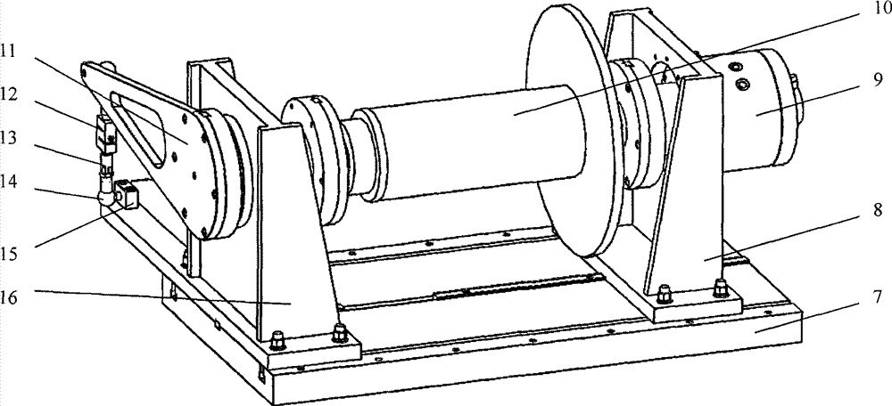
[0024] see figure 2 , the bottom plate 7 is a thick steel plate, which is fixed on the platform; there is a flat keyway running through the middle of the upper surface of the bottom plate, the flat key is installed in the flat keyway and fixed with bolts, and there is a longitudinally running T-slot on both sides of the flat keyway , the T...


PUM


Abstract

The invention relates to a wind driven generator coupler slipping torque calibration test bed and calibration method which is particularly suitable for stimulating actual working environment to conduct a slipping torque calibration test when a wind driven generator coupler is developed and leaves a factory. The test bed is mainly composed of a rack, a base plate, a torque loading mechanism, a torque output detecting mechanism, a hydraulic system and a computer control system. When the test is conducted, firstly the wind driven generator coupler is installed on the test bed, a hydraulic swing oil cylinder is started, the wind driven generator coupler is loaded by the torque loading mechanism, the load is acted on a tension and pressure sensor through the torque output detecting mechanism, transmission torque is obtained through indirect detection, and when a torque limiter of the wind driven generator coupler slips, the computer control system monitors that torque in a torque-angle curve suddenly changes, and the torque is the slipping torque of the wind driven generator coupler. The wind driven generator coupler slipping torque calibration test bed and calibration method is also suitable for slipping torque calibration of couplers and transmission shafts of other types.

Description

technical field [0001] The invention relates to a wind turbine coupling slip torque calibration test bench and a calibration method, which are especially suitable for simulating the actual working environment for the slip torque calibration test in the development and delivery of the wind turbine coupling. Background technique [0002] The wind turbine relies on the wind to drive the propeller to rotate, increases the speed through the gear box, and connects the output shaft of the gear box and the rotor shaft of the generator through the wind turbine coupling to convert the wind energy into electrical energy. When the transmission torque of the wind turbine exceeds its limit, the torque limiter on the coupling of the wind turbine generator slips to protect it from damage. During the development and delivery of the wind turbine coupling, the slip torque needs to be calibrated to meet the stable operation requirements of the wind turbine system. The problems existing in the ...

Claims


Application Information

Patent Timeline
Patent Type & Authority Applications(China)
IPC IPC(8): G01M13/02G01L3/00
Inventor 杨孟涛唐家兵金红伟
Owner CHONGQING UNIVERSITY OF SCIENCE AND TECHNOLOGY
Why Eureka
Try Eureka