Metal porous membrane preparation method and device based on laser shock wave effect

A metal porous and shock wave technology, applied in chemical instruments and methods, membrane technology, semi-permeable membrane separation, etc., can solve problems such as complex processes, achieve good toughness, avoid cracking, and avoid deceleration

Inactive Publication Date: 2013-10-02
JIANGSU UNIV
View PDF1 Cites 8 Cited by
  • Summary
  • Abstract
  • Description
  • Claims
  • Application Information

AI Technical Summary

Problems solved by technology

These methods generally have the disadvantage of complex process, and can only prepare limited varieties of metal porous membranes, such as stainless steel porous membranes, the above methods are not competent

Method used


Image

  • Metal porous membrane preparation method and device based on laser shock wave effect

Examples


Embodiment 1

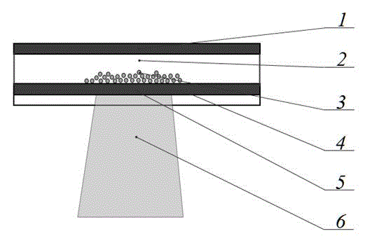
[0023] The metal film 1 described in this example is a stainless steel film with a thickness of 10 μm; the hard microparticle 3 is a SiC particle with a particle size of 10 nm; the absorption layer 4 is an aluminum foil with a thickness of 100 μm; the constrained layer 5 is K9 with a thickness of 3 mm. Optical glass; high-energy pulsed laser 6 is a pulsed laser with a pulse width of 10 ns and a maximum pulse energy of 12J.

[0024] Implement a kind of metal porous film preparation method based on laser shock wave effect of the present invention to carry out the following steps:

[0025] 1) Covering the absorbing layer 4 on the surface of the constraining layer 5;

[0026] 2) covering the surface of the absorbing layer 4 with a layer of hard microparticles 3 with a thickness of about 1 μm;

[0027] 3) placing the metal thin film 1 at a position about 2 mm above the absorbing layer 4;

[0028] 4) Place the whole device in the vacuum chamber 2;

[0029] 5) The high-energy puls...

Embodiment 2

[0033] The metal film 1 described in this example is a titanium film with a thickness of 50 μm; the hard microparticle 3 is a WC particle with a particle size of 0.2 μm; the absorption layer 4 is an aluminum foil with a thickness of 100 μm; K9 optical glass; high-energy pulse laser 6 is a pulse laser with a pulse width of 20ns and a maximum pulse energy of 12J.

[0034] Implement a kind of metal porous film preparation method based on laser shock wave effect of the present invention to carry out the following steps:

[0035] 1) Covering the absorbing layer 4 on the surface of the constraining layer 5;

[0036] 2) covering the surface of the absorbing layer 4 with a layer of hard microparticles 3 with a thickness of about 1 μm;

[0037] 3) placing the metal film 1 at a position about 5 mm above the absorbing layer 4;

[0038] 4) Place the whole device in the vacuum chamber 2;

[0039] 5) The high-energy pulsed laser 6 passes through the constrained layer 5 and irradiates on ...

Embodiment 3

[0043] The metal film 1 described in this example is a nickel film with a thickness of 100 μm; the hard microparticle 3 is a SiC particle with a particle size of 10 μm; the absorption layer 4 is an aluminum foil with a thickness of 100 μm; the constrained layer 5 is K9 with a thickness of 3 mm Optical glass; high-energy pulsed laser 6 is a pulsed laser with a pulse width of 30ns and a maximum pulse energy of 12J.

[0044] Implement a kind of metal porous film preparation method based on laser shock wave effect of the present invention to carry out the following steps:

[0045] 1) Covering the absorbing layer 4 on the surface of the constraining layer 5;

[0046] 2) covering the surface of the absorbing layer 4 with a layer of hard microparticles 3 with a thickness of about 1 μm;

[0047] 3) placing the metal thin film 1 at a position about 2 mm above the absorbing layer 4;

[0048] 4) Place the whole device in the vacuum chamber 2;

[0049] 5) The high-energy pulsed laser 6...


PUM

PropertyMeasurementUnit
energyaaaaaaaaaa
thicknessaaaaaaaaaa
thicknessaaaaaaaaaa

Abstract

The invention discloses a metal porous membrane preparation method and device based on a laser shock wave effect. The device comprises a metal thin membrane, a vacuum cavity, hard micro particles, an absorbing layer, a restraint layer and a high energy pulse laser. The high energy pulse laser penetrates the restraint layer, and is interacted with the absorbing layer to generate plasma explosion; the restraint layer can restrain the explosion of plasma, prolongs the explosion time of the plasma and improves peak pressure generated by the explosion of the plasma; as the peak pressure generated by the explosion of plasma is extremely high and can reach a couple of GPa even dozens of GPa, so that the shock waves are formed; the shock waves penetrate the absorption layer and drive the hard micro particles placed at the back of the absorption layer; under the vacuum environment, the hard micro particles penetrate the metal thin membrane at extremely high speed, so that the metal porous membrane is formed. The method and the device can be applied to the preparation of metal porous membranes adopting any metal materials.

Description

technical field [0001] The invention belongs to the technical field of laser processing, and in particular relates to the preparation technology of metal porous membranes. Background technique [0002] Membrane separation technology has attracted great attention from governments and many industries for its superior performance such as low-temperature non-phase-change operation, low energy consumption, high efficiency, and less loss of active ingredients in materials. It has become one of the most successful and promising high-tech technologies in the contemporary era. . Practice has proved that the development of membrane materials and membrane separation technology is inseparable. The new development of membrane materials has promoted the improvement of membrane separation technology, and the expansion of the application range of membrane separation technology has put forward new requirements for membrane materials. Commonly used separation membranes mainly include organi...

Claims


Application Information

Patent Timeline
Patent Type & Authority Applications(China)
IPC IPC(8): B01D71/02B01D67/00
Inventor 戴峰泽温德平于璐张永康
Owner JIANGSU UNIV
Why Eureka
Try Eureka