Compression forming mold for sintered metal product, application thereof and forming mold release method

A technology of powder metallurgy and compression molding, applied in the field of powder metallurgy, which can solve the problems of complex mold structure and molding process, poor compact strength, and affecting the rate of genuine products, so as to achieve good surface quality, low demoulding pressure, and reduce production costs Effect

Active Publication Date: 2013-10-02
YIYANG XINJIYUAN POWDER METALLURGY
View PDF9 Cites 10 Cited by
  • Summary
  • Abstract
  • Description
  • Claims
  • Application Information

AI Technical Summary

Problems solved by technology

[0003] 1. The complex shape of the product makes the mold structure and molding process action very complicated;
[0004] 2. The density of the product is high, and the requirements for the mold material are increased. Usually, the mold material needs to be expensive steel-bonded alloy or hard alloy;
[0005] 3. The higher the length-to-diameter ratio of the product, the larger the corresponding side area of ​​the product will be. Because of the side pressure, the demoulding pressure will be very high, and even the demoulding pressure will exceed the pressing pressure, and the demoulding pressure will The larger it is, the more defects of cracking and straining will occur in the molded products, which will affect the authenticity rate;
[0006] 4. When the compressibility and formability of the powder material itself is very poor, such as Fe-Si, Fe-Si-Al, Fe-Si-Cr and other soft magnetic powders, amorphous soft magnetic powders, spherical soft magnetic powders, stainless steel powders, etc., because The shape of the powder itself is very regular, and the hardness is very high. Therefore, when pressing, the pressure must be large enough, and the mold material must be very good; If the press formability is poor, the strength of the compact is also poor. Therefore, if a conventional molding method and mold are used (the female mold is an integral structure, when demolding, the workpiece is ejected from the female mold by the lower punch, or the female mold Pull down in the direction of punching to make the workpiece out of the female die mouth), excessive demoulding pressure, that is, the friction between the female mold wall and the outer wall of the workpiece, and the high heat and high temperature generated by the friction will in turn "formed" The workpiece" is broken, cracked, and scaled out during the demoulding process, making the workpiece scrapped

Method used


Image

  • Compression forming mold for sintered metal product, application thereof and forming mold release method
  • Compression forming mold for sintered metal product, application thereof and forming mold release method
  • Compression forming mold for sintered metal product, application thereof and forming mold release method

Examples


Embodiment 1

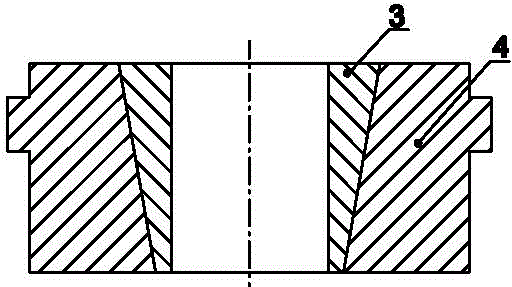
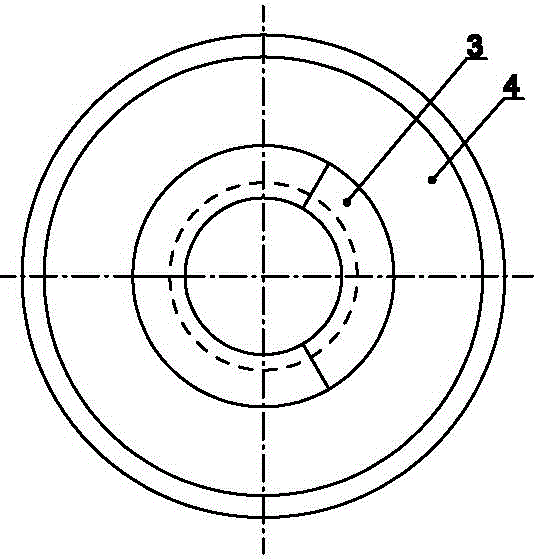
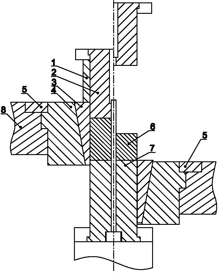
[0033] Depend on figure 1 , figure 2 It can be seen that a powder metallurgy product compression molding mold includes a female mold, and the female mold is a split structure, which includes a female mold cover 4, a female mold core composed of at least two female mold core valves 3 , the outer surface of the female mold core and the inner surface of the female mold sheath 4 are tapered, and the female mold core is a cone-shaped body with a large top and a small bottom along the pressing direction.

[0034] For the convenience of processing, the size and shape of each female mold core flap 3 of the present invention are consistent.

[0035] The cone angle of the female mold core of the present invention is 14°-30°, preferably 16°-20°.

[0036] Present embodiment female mold core valve 3 is 3, and its size, shape are consistent, and the formed female mold core is a cone frustum, and its cone angle is 20 °.

[0037] An application of the above-mentioned powder metallurgy pro...

Embodiment 2

[0049] Depend on Figure 4 It can be seen that there are two female mold core flaps 3 in this embodiment, which are consistent in size and shape. The formed female mold core is a truncated cone with a cone angle of 18°, and the processed workpiece 6 has a quincunx-shaped cross section. columnar parts. The rest are the same as embodiment 1.

Embodiment 3

[0051] Depend on Figure 5 It can be seen that there are four female mold core flaps 3 in this embodiment, which are consistent in size and shape. The formed female mold core is a truncated cone with a cone angle of 20°, and the processed workpiece 6 is square in cross section. Columnar parts. The rest are the same as embodiment 1.


PUM

PropertyMeasurementUnit
angleaaaaaaaaaa
angleaaaaaaaaaa

Abstract

The invention discloses a compression forming mold for a sintered metal product, application of the compression forming mold for the sintered metal product, and a forming mold release method. The compression forming mold for the sintered metal product comprises a female mold. The compression forming mold for the sintered metal product is characterized in that the female mold is of a split structure, and comprises a female mold covering sleeve (4) and a female mold core which is composed of at least two female mold core clacks (3), wherein the outer side face of the female mold core and the inner side face of the female mold covering sleeve (4) are in conical surface matching, and the female mold core is a big-end-up cone-shaped body in the compression direction. The forming mold release method comprises the steps of mold filling, compression forming and mold release. The compression forming mold for the sintered metal product facilitates the mold filling and the mold release, is low in pressure of the mold release, particularly applicable to the compression forming and the mold release of the sintered metal product which is poor in compressibility and formability of powder materials, long in service life, and low in manufacturing cost, reduces the requirement for a press and manufacturing cost, and reduces production cost due to the fact that consumption of forming agents and consumption of lubricating agents are greatly reduced. Meanwhile, the surface of the sintered metal product is complete, the rate of quality products is greatly improved, and the forming problem of the sintered metal product which is poor in compression formability and complex in shape is solved.

Description

technical field [0001] The present invention relates to the field of powder metallurgy, in particular to a powder metallurgy product compression molding die and its application and a molding and demoulding method, in particular to a powder metallurgy product compression molding die with poor compressibility and molding performance of powder materials and its application and molding release methods. Background technique [0002] In the field of powder metallurgy, forming methods and forming dies are a very critical link. Especially for powder materials with large aspect ratio (ratio of length to diameter), complex shape (with steps inside and outside), high density requirements (relative density over 90%), and poor formability (such as magnetic powder, stainless steel powder etc.) and other powder metallurgy products are difficult or even impossible to form using conventional molding processes and molds. The main reasons are: [0003] 1. The complex shape of the product mak...

Claims


Application Information

Patent Timeline
Patent Type & Authority Applications(China)
IPC IPC(8): B22F3/03
Inventor 蔡建良黄志平
Owner YIYANG XINJIYUAN POWDER METALLURGY
Why Eureka
Try Eureka