
Belt type carrier-based aircraft booster system and decentralized energy storage and concentrated random boosting working method

A carrier-based aircraft and booster technology, which is applied in the launch/tug transmission device and other directions, can solve the problems of consuming aircraft carrier boilers, uneconomical, large initial energy, etc., and achieves accelerated humanization, space saving, and scientific and reasonable design. Effect

Active Publication Date: 2013-10-02
如东县岔河污水处理有限公司
View PDF5 Cites 22 Cited by
  • Summary
  • Abstract
  • Description
  • Claims
  • Application Information

AI Technical Summary

Problems solved by technology

[0005]2) High requirements on materials and workmanship
And converting this steam into propulsion is only 4% to 6%! If the boost is carried out at the minimum interval, it needs to consume 20% of the steam of the aircraft carrier boiler;
[0007]4) The system is complicated and there are many operators. One booster needs about 120 operators and maintenance personnel
[0009]6) The cost is high, and the production technology is highly confidential. It is known that a steam catapult in active service in the United States costs at least 80 million US dollars. Currently, only the United States has the production technology and sales The scope of use is only the United States and its allies
[0010]The second is the electromagnetic catapult. In view of the various defects of the steam catapult, the U.S. Navy spent 28 years and cost 3.2 billion US dollars to successfully develop the electromagnetic catapult. Although the catapult has been successfully tested on land, it is still in the research stage due to its large size, huge power consumption, complicated structure, unreliable stability, and inability to adapt to the harsh environment of humidity and salt spray at sea. However, the U.S. military has not yet dared to formally equip an aircraft carrier
Regardless of the steam catapult or the electromagnetic catapult, the instantaneous release of huge energy is achieved through energy storage, and the power consumption is 64,000 kilowatts. The steam catapult stores energy through two 100 cubic meter steam storage tanks. The high-pressure steam is converted into mechanical kinetic energy through the open cylinder; the electromagnetic catapult is realized by means of a forced energy storage power station. The so-called forced energy storage power station is to drive the electric energy of the traditional power station to rotate eight 8000 kilowatt dual-purpose motors for storage. Energy, when the electromagnetic catapult needs a large current to do work, the 8 motors are immediately converted into 8 generators to convert the rotational potential energy into electrical energy, and the electrical energy is concentrated in the linear motor of the electromagnetic catapult to convert it into magnetic energy. The high-speed movement of the child is converted into kinetic energy, and the energy will consume 30-50% in the process of multiple conversions. Since steam catapults and electromagnetic catapults perform instantaneous work through steam pressure energy and magnetic field potential energy, the initial energy is large, so the energy The waste is huge. According to relevant reports, less than 10% of the energy actually used on the carrier-based aircraft is the least economical of the two ejection modes.

Method used


Image

  • Belt type carrier-based aircraft booster system and decentralized energy storage and concentrated random boosting working method
  • Belt type carrier-based aircraft booster system and decentralized energy storage and concentrated random boosting working method
  • Belt type carrier-based aircraft booster system and decentralized energy storage and concentrated random boosting working method

Examples


Embodiment

[0073] The design steps are as follows:

[0074] The carrier-based aircraft must obtain 30m / s on a runway of 100m 2 Acceleration can take off, the aircraft takeoff speed and acceleration movement time calculation formula is as follows:

[0075] V=√(2aL)=√(200×30)≈77.46m / s (1)

[0076] t=√(2L / a)=√(200 / 30)≈2.58s (2)

[0077] The length of the drive belt = the length of the runway, L = the sum of the lengths of the drive belts wound on the drive shaft, the length of the drive belt

[0078] L=(L1+L2+…LN)=100m=length of booster runway (3)

[0079] The formula for calculating the length of each layer of drive belt on the drive shaft: Li=3.14(D+2dn) (4)

[0080] D is the diameter of the drive shaft,

[0081] d = thickness of the drive belt;

[0082] n = number of layers of belt

[0083] L=100=3.14[(D+2d1)+(D+2d2)+(D+2d3)+...(D+2dn)] (5)

[0084] The length of the known booster runway = the length of the transmission belt = 100 meters, ignoring the winding density o...


PUM


Abstract

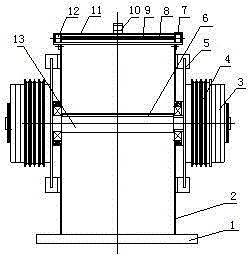
The invention provides a belt type carrier-based aircraft booster system and a decentralized energy storage and concentrated random boosting working method. The system comprises a boosting module assembly, a return module assembly, a runway module, a slide shuttle module and a controller module, wherein the boosting module assembly consists of more than one boosting module which is arranged below the runway module; the boosting module comprises a T-shaped box body, motors, a transmission shaft, a clutch, a brake and a pedestal; the bottom of the T-shaped box body is fixed to the middle part of the pedestal; the motors are fixedly arranged on the pedestal and are positioned on the two sides of the T-shaped box body; the transmission shaft penetrates through the middle part of the T-shaped box body through a bearing pedestal; the two ends of the transmission shaft are provided with the clutch and the brake respectively; a driven part of the clutch and the brake are fixed to the transmission shaft; a driving part of the clutch is connected with the belt pulley; the belt pulley is connected with the transmission shaft through a bearing; the outer circle of the belt pulley is connected with the belt pulley at the motor shaft end through the belt; and the two ends of the folded transmission belt are fixed on the transmission shaft in the middle of the T-shaped box body through belt pressing plates. The system has the characteristics of simple structure, easiness in machining, transportation, mounting, debugging and maintenance, high modularization and the like, and is a piece of optimal equipment for an aircraft carrier.

Description

technical field [0001] The invention relates to the technical field of military equipment, in particular to a belt-type carrier-based aircraft booster system and a distributed energy storage centralized random booster method. Background technique [0002] At present, there are mainly two types of carrier-based aircraft catapults used on aircraft carriers. One is the steam catapult used on US aircraft carriers. The booster uses steam as power to drive the traction hook through the piston in the open cylinder to pull the aircraft to accelerate take-off . The steam catapult equipment is bulky, takes up a lot of space, the manufacturing process is complicated, and consumes a lot of fresh water. Because the steam catapult in the United States uses a slotted cylinder, the steam leakage is large and the energy consumption is large. The cylinder seal uses The service life is short, and the maintenance cost is high. In severe cold regions or in winter, the leaked steam will freeze o...

Claims


Application Information

Patent Timeline
Patent Type & Authority Applications(China)
IPC IPC(8): B64F1/04
CPCB64F1/08B64F1/06
Inventor 姜明邱玉成霍刚姜鹏
Owner 如东县岔河污水处理有限公司
Learn More