Backlight module of display device and white light LED

The technology of a backlight module and a display device is applied to the backlight module and white LED. field, it can solve the problems such as the reduction of luminous efficiency

Inactive Publication Date: 2013-10-09
SHENZHEN CHINA STAR OPTOELECTRONICS TECH CO LTD
View PDF6 Cites 41 Cited by
  • Summary
  • Abstract
  • Description
  • Claims
  • Application Information

AI Technical Summary

Problems solved by technology

However, this method will cause the reabsorption of the RG

Method used


Image

  • Backlight module of display device and white light LED
  • Backlight module of display device and white light LED
  • Backlight module of display device and white light LED

Examples


Embodiment 1

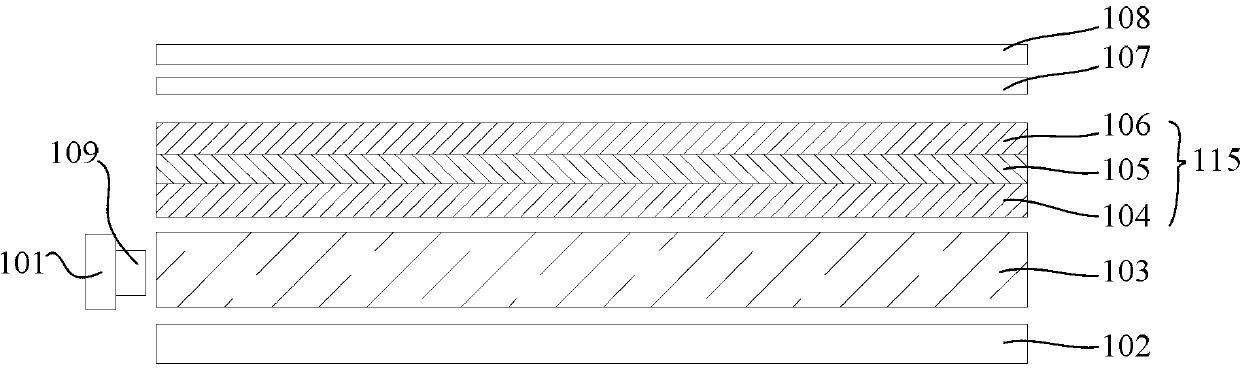
[0029] Such as figure 1 As shown, this embodiment provides a backlight module for a display device, the backlight module includes: a light bar 101 and a light guide plate 103; the light bar 101 is provided with a plurality of ultraviolet LEDs 109, and the The light incident surface is arranged opposite to the ultraviolet light LED 109; the light emitted by the ultraviolet light LED 109 includes an RGB quantum dot phosphor layer 115 in the path of the light emitted from the light exit surface of the light guide plate 103; the RGB The quantum dot phosphor layer 115 includes a red light quantum dot fluorescent film 104 , a green light quantum dot fluorescent film 105 and a blue light quantum dot fluorescent film 106 arranged in sequence. The RGB quantum dot phosphor layer 115 produces white light under the excitation of ultraviolet light emitted by the ultraviolet light LED 109, which improves the color saturation of the backlight module, and because the RGB quantum dot phosphor ...

Embodiment 2

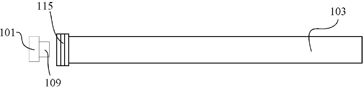
[0033] Such as figure 2 As shown, the difference from Embodiment 1 is that the RGB quantum dot phosphor layer 115 is arranged on the light incident surface of the light guide plate 103, and the light of the ultraviolet light LED 109 of the backlight module mainly enters from the light incident surface of the light guide plate 103 and then It is emitted from the light-emitting surface, so the RGB quantum dot phosphor layer 115 is provided on the light-incident surface to ensure that the light emitted from the light-emitting surface of the light guide plate is also white light. The RGB quantum dot phosphor layer is also formed by sequentially setting the red light quantum dot fluorescent film 104 , the green light quantum dot fluorescent film 105 and the blue light quantum dot fluorescent film 106 in the light irradiation direction.

Embodiment 3

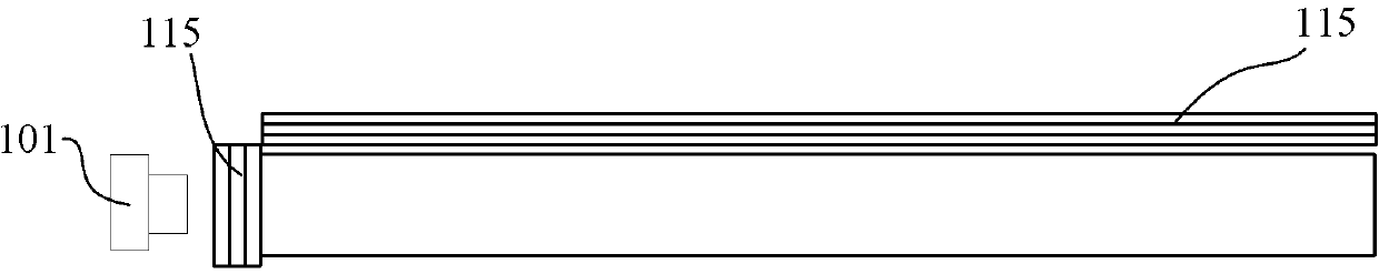
[0035] Such as image 3 As shown, the difference from Embodiment 1 and Embodiment 2 is that RGB quantum dot phosphor layers 115 are provided on both the light incident surface and the light exit surface of the light guide plate 103, thus ensuring that the light emitted from the light guide plate 103 is pure white light.


PUM

PropertyMeasurementUnit
Emission wavelengthaaaaaaaaaa

Abstract

The invention discloses a backlight module of a display device and a white light LED. The backlight module comprises a lamp bar and a light guide plate, wherein the lamp bar is provided with a plurality of ultraviolet light LEDs, and the light-entering face of the light guide plate and the ultraviolet light LEDs are arranged oppositely. A path of the process from light emitted by the ultraviolet light LEDs to the light shot from the light-exiting face of the light guide plate at least comprises an RGB quantum dot fluorescent powder layer. The RGB quantum dot fluorescent powder layer comprises a red light quantum dot fluorescent screen, a green light quantum dot fluorescent screen and a blue light quantum dot fluorescent screen, wherein the red light quantum dot fluorescent screen, the green light quantum dot fluorescent screen and the blue light quantum dot fluorescent screen are sequentially arranged. The RGB quantum dot fluorescent powder layer generates high-purity white light under excitation of ultraviolet light emitted by the ultraviolet light LEDs. As the RGB quantum dot fluorescent powder layer is formed by sequentially arranging the red light quantum dot fluorescent screen, the green light quantum dot fluorescent screen and the blue light quantum dot fluorescent screen, color saturation of the backlight module is improved, and the problem of reabsorption of RGB quantum dot fluorescent powder is solved.

Description

technical field [0001] The present invention relates to the field of display devices, more specifically, to a backlight module and a white LED of a display device. Background technique [0002] At present, for color TFT-LCD display components, white light LEDs are commonly used together with color RGB photoresists to realize color display of TFT-LCD components. In order for TFT-LCD components to display richer colors, that is, to achieve a larger area of ​​color gamut coverage in the CIE color coordinates, white LEDs with higher RGB color purity are required. [0003] There are two main ways to achieve high color purity of white LEDs: one is to use RGB three-color chip LEDs, and the other is to use blue light chips plus RG phosphors. Among them, although the RGB three-color chip LED method can achieve high-purity white light, this method has different lifetimes of the RGB three-color chips, especially the green chip has the fastest life decay, which directly affects the att...

Claims


Application Information

Patent Timeline
IPC IPC(8): F21V13/00F21V9/16G02F1/13357F21Y101/02
CPCG02F1/133615G02F2202/36G02F1/133614H01L33/504
Inventor 胡哲彰樊勇
Owner SHENZHEN CHINA STAR OPTOELECTRONICS TECH CO LTD
Why Eureka
Try Eureka