
Optical gain performance test device of organic film

A test device and organic thin film technology, applied in the direction of color/spectral characteristic measurement, etc., can solve the problems of light intensity loss, unstable measurement of pump light source, error, etc., and achieve the effect of a reliable design method

Active Publication Date: 2013-10-09
安第斯新材料科技(浙江)有限公司
View PDF0 Cites 5 Cited by
  • Summary
  • Abstract
  • Description
  • Claims
  • Application Information

AI Technical Summary

Problems solved by technology

The optical path design strives to solve the measurement error caused by the instability of the pump light source that is common in similar measurements; each optical reflection surface forms multiple spots on the sample after multiple reflections of the incident light; light intensity loss occurs when the polarization direction of the incident light is changed. 50%; When measuring different optical properties, it is necessary to rebuild the optical path, perform complex and time-consuming collimation adjustments, and many other technical problems

Method used


Image

  • Optical gain performance test device of organic film
  • Optical gain performance test device of organic film
  • Optical gain performance test device of organic film

Examples


Embodiment 1

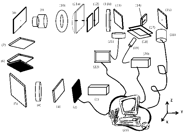
[0028] Measure the relationship between the ASE performance of the thin film material and the polarization direction of the pump light source with the optical path designed by the present invention: figure 1 Put the element into the light path, rotate the linear polarizer to the required direction, continuously reduce the full-wave attenuation plate, and make the pump light intensity from weak to strong, measure and record the sample spectrum as the incident light intensity changes, determine the ASE threshold, and then Put a half-wave plate into the optical path to change the polarization direction of the incident light by 90 o , keeping other components on the optical path unchanged, repeat the above measurement.

Embodiment 2

[0030] Measure the loss coefficient of thin film material with the optical path of the present invention design: press figure 1 Designing the optical path, this measurement does not require a linear polarizer and a half-wave plate, so these two components can be moved out of the optical path. Under a specific incident light intensity, the adjustable slit width is fixed, the position of the spectrometer probe is fixed, the sample is adjusted so that one edge of the rectangular spot is just at the edge of the sample, the ASE signal intensity and spectrum of the sample are recorded, and then the sample is moved to make the edge of the rectangular spot Move into the sample, such as 0.1mm, record the ASE signal intensity and spectrum of the sample again, continue to move the edge of the rectangular spot to the sample for the same distance, that is, 0.1mm, record the ASE signal intensity and spectrum of the sample, and repeat the measurement to obtain a set of The relationship curv...


PUM


Abstract

The invention provides an optical gain performance test device of an organic film. The test device comprises a pulse laser device (1), an optical path switch (2), a linear polarization plate (3), one half wave plate (4), a first reflective mirror (5), a full-wave attenuation plate (6), a pass-band filter plate (7), a second reflective mirror (8), a zooming beam expander (9), an adjustable aperture (10), a cylindrical concave lens (11a), an adjustable silt (12), a spherical lens (11b), a 9:1 beam splitter (13), a sample illumination bar-shaped region (14) and a third reflective mirror (15), which are sequentially arranged on the same optical path. The optical gain performance test device of the organic film can be utilized for accurately measuring the spontaneous radiation amplification performance, the optical gain coefficient, the loss coefficient, the polarization spectroscopy change of the film as well as the threshold value, the efficient and the like of the organic film.

Description

technical field [0001] The invention belongs to the technical field of organic and polymer luminescent performance test instrument design, and is a specially designed optical path design for optical gain performance test of organic and polymer thin film laser materials and devices. Background technique [0002] The polymer semiconductor light-emitting device has the advantages of simple manufacturing process, large-area processing, and can be fabricated on a bendable flexible substrate by ink-jet technology. Moreover, the emission spectrum range of organic luminescent materials is wide, and organic light pumping lasers in the visible light range of 400-700 nanometers have been reported, and plastic optical fibers made of (poly(methylmethacrylate), (PMMA) have a low loss window Just in the 520-580nm and 650nm bands. Therefore, the development of low-cost, high-efficiency, high-stability organic semiconductor laser devices, as a new generation of optical communication light so...

Claims


Application Information

Patent Timeline
IPC IPC(8): G01N21/25
Inventor 夏瑞东
Owner 安第斯新材料科技(浙江)有限公司
Learn More