Flue gas denitrification monitoring system and method

A monitoring system and flue gas technology, applied in the field of flue gas denitrification monitoring system, can solve the problems of high water content, high dust, large detection error, etc., and achieve the effects of low cost, improved service life, and reduced impact

Active Publication Date: 2013-10-09
FOCUSED PHOTONICS
View PDF7 Cites 7 Cited by
  • Summary
  • Abstract
  • Description
  • Claims
  • Application Information

AI Technical Summary

Problems solved by technology

[0009] In order to solve the deficiencies in the above-mentioned existing technical solutions, the present invention provides a flue gas denitrification monitoring system, which solves technical problems such as high dust, high water content, and large detection errors in the field of flue gas denitrification, thereby realizing Invention purpose of low-cost, continuous, high-precision and rapid monitoring of components in flue gas

Method used


Image

  • Flue gas denitrification monitoring system and method
  • Flue gas denitrification monitoring system and method

Examples


Embodiment 1

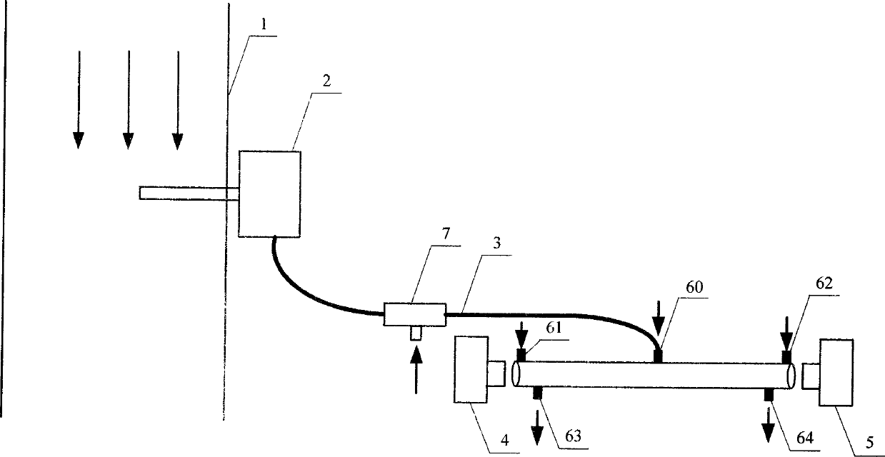
[0038] figure 1 Schematically provides a simplified structural diagram of the flue gas denitrification monitoring system of the embodiment of the present invention, as figure 1 As shown, the flue gas denitrification monitoring system includes:

[0039] The sampling device, the filtering device 2, the gas chamber and the analysis instrument are all prior art in this field, and will not be repeated here. The sampling device is installed on the flue 1.

[0040] A heating device, the heating device is used to heat the filter device, the gas chamber, and the pipeline connecting the filter device and the gas chamber; preferably, the temperature of the flue gas in the filter device 2, the pipeline 3 and the gas chamber exceeds 200°C by heating.

[0041] Isolation device, the isolation device is used to provide gas, the gas enters the gas chamber from the air inlet 61, forms an isolation area on the side of the optical component adjacent to the smoke, isolates the optical component ...

Embodiment 2

[0058] An application example of the flue gas denitrification monitoring system and method according to Embodiment 1 of the present invention in the monitoring of escaped ammonia.

[0059] In the flue gas denitrification monitoring system of this application example, the filter device adopts a ceramic filter with a filtration accuracy of 20 μm; an electric heating block is installed in the box of the filter device, an electric heating cable is installed on the pipeline, and the gas chamber is made of stainless steel. Cartridge, mounted in a box with an electric heating block. The two ends of the gas chamber are respectively provided with optical windows and reflectors, and the air inlets for the isolation gas are arranged on the gas chamber on the side of the optical windows and reflectors adjacent to the flue gas. The gas chamber between the gas ports (such as the middle of the gas chamber on the same side as the air inlet) is provided with a smoke inlet, and the two exhaust ...

Embodiment 3

[0065] An application example of the flue gas denitrification monitoring system and method according to Embodiment 1 of the present invention in the monitoring of escaped ammonia.

[0066] In the flue gas denitrification monitoring system of this application example, the filter device adopts a silk filter with a filtration accuracy of 8μn; an electric heating block is installed in the filter device, an electric heating cable is installed on the pipeline, and a cylinder made of stainless steel is used in the gas chamber. Installed in a box with electric heating block. The two ends of the gas chamber are respectively provided with a first optical window and a second optical window, and the gas chamber on the side of the first optical window and the second optical window adjacent to the flue gas is provided for the passage of isolation gas. The gas inlet is set on the gas chamber between the two gas inlets (such as in the middle of the gas chamber on the same side as the gas inle...


PUM


Abstract

The invention provides a flue gas denitrification monitoring system which comprises a sampling device, a filter device, a gas chamber, an analysis meter, an isolation device, a heater and a cleaning plant, wherein the isolation device is used for supplying gas; the gas enters the gas chamber via a gas inlet, forms an isolation region on one side of an optical component adjacent to the flue gas, and is discharged out of the gas chamber via a gas outlet; the heater is used for heating the filter device, the gas chamber and a pipeline connecting the filter device and gas chamber; the cleaning plant comprises a main body, and a first channel, a second channel and a third channel which are arranged in the main body and communicated with each other; the first channel is communicated with the filter device, the second channel is communicated with the gas chamber, and the third channel is communicated with a gas source; the first channel is provided with an expansion region; the included angle between the first channel and the second channel is an obtuse angle or right angle; and the included angle between the second channel and third channel is an acute angle or right angle. The invention has the advantages of high detection speed, high precision, long continuous working time and the like.

Description

technical field [0001] The invention relates to gas monitoring, in particular to a flue gas denitrification monitoring system and method. Background technique [0002] In flue gas SCR (or SNCR) process denitrification technology, ammonia gas is used to react with nitrogen oxides to generate water and nitrogen gas, so as to meet environmental protection requirements. In order to control the amount of ammonia gas injected into the raw material and prevent excessive ammonia gas from reacting with the sample gas to form solid matter and block the air preheater or optical window at the rear end, it is necessary to monitor the escaped ammonia in the flue gas pipeline at the outlet of the denitrification device to form a closed loop Control the ammonia injection volume of the denitrification device. [0003] In the above-mentioned monitoring of flue gas denitrification escape ammonia, the working conditions are relatively bad: [0004] 1. The dust content in the flue gas is very ...

Claims


Application Information

Patent Timeline
Patent Type & Authority Applications(China)
IPC IPC(8): G01N21/31
Inventor 陈生龙俞大海郑利武张飞顾海涛
Owner FOCUSED PHOTONICS
Why Eureka
Try Eureka