Flue gas semidry desulfurization method and device

A semi-dry desulfurization and flue gas technology, applied in separation methods, chemical instruments and methods, dispersed particle separation, etc. It can avoid scaling and clogging, improve desulfurization efficiency, and ensure desulfurization efficiency.

Inactive Publication Date: 2013-10-16
TIANJIN UNIV
View PDF1 Cites 6 Cited by
  • Summary
  • Abstract
  • Description
  • Claims
  • Application Information

AI Technical Summary

Problems solved by technology

[0004] The desulfurization process adopts the ordinary semi-dry desulfurization method, which has fast reaction speed, low processing cost, and the desulfurization product is easy to handle. However, the desulfurization efficiency of the ordinary semi-dry method is low. The desulfurization efficiency can be improved by spraying humidification, and it is easy to form wet ash clusters and pulp lumps, resulting in poor system operation

Method used


Image

  • Flue gas semidry desulfurization method and device
  • Flue gas semidry desulfurization method and device

Examples


Embodiment 1

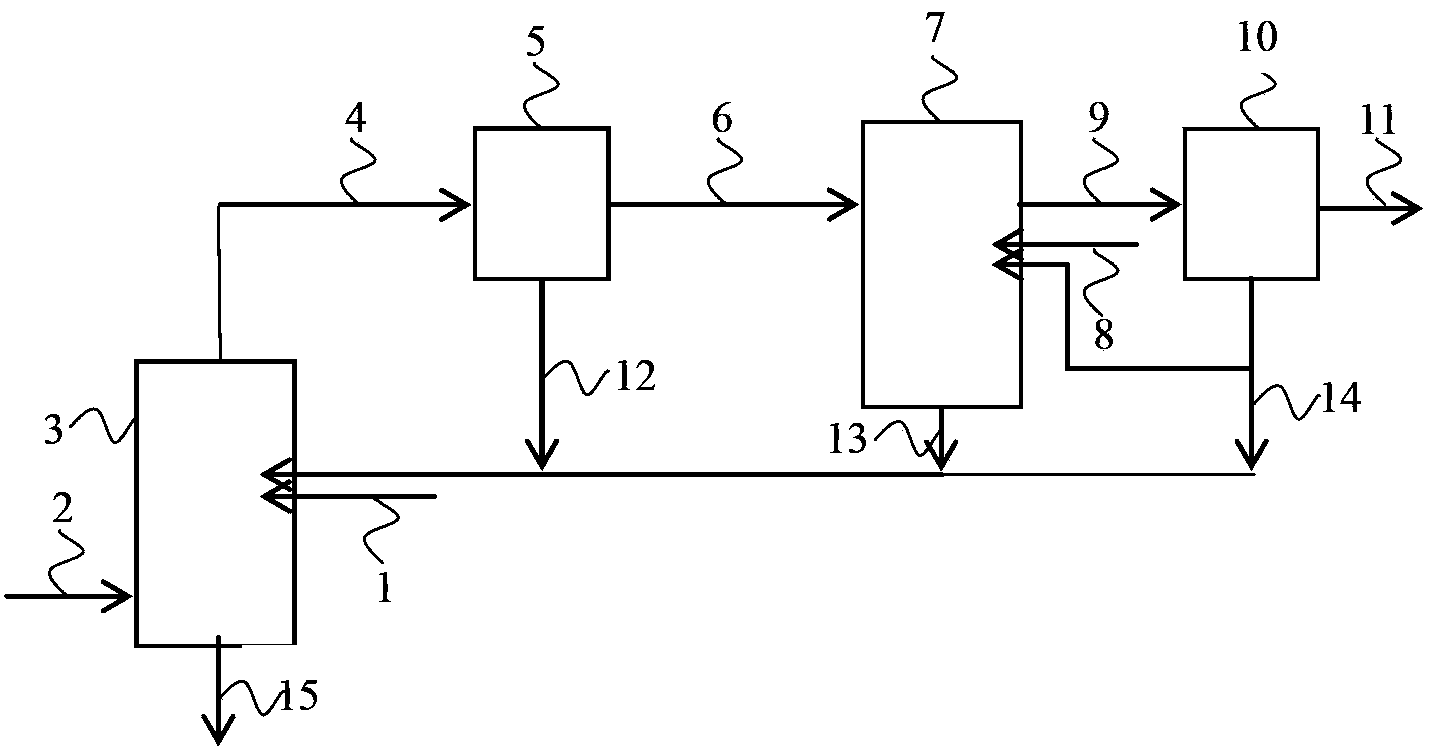
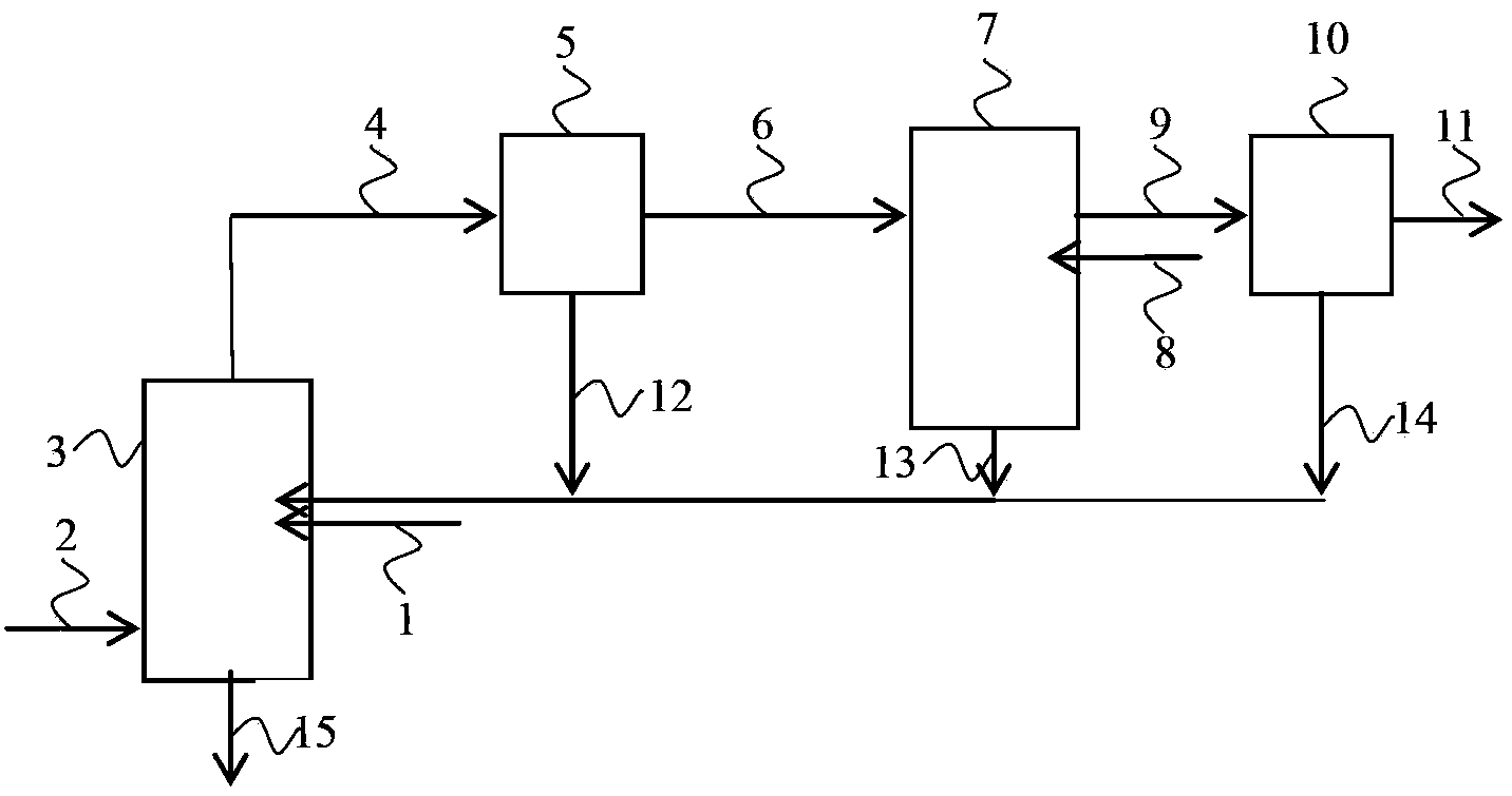
[0035] Such as figure 1 Shown is an example of a process flow diagram of a treatment method represented by an embodiment of the present invention. Calcium oxide dry powder desulfurization agent according to the requirement of calcium sulfur ratio 1.1 (the amount is calculated according to the flue gas volume and the concentration of sulfur dioxide in the flue gas), through the desulfurizer inlet 1, the flue gas adjusted to 5% by water steam passes through the flue gas The gas inlet 2 enters the front-stage desulfurization tower 3, and contacts and reacts in the front-stage desulfurization tower 3. After the reaction, the flue gas that has been desulfurized once passes through the flue gas inlet 4 of the front-stage dust collector, and is dust-removed in the front-stage dust collector 5. The flue gas after dust removal The gas passes through the flue gas inlet 6 of the rear-stage desulfurization tower after being conditioned by water steam, and then enters the rear-stage desulf...

Embodiment 2

[0037] The desulfurization process flow is basically the same as in Example 1, except that figure 1 The desulfurizing agent recovered as shown, the desulfurizing agent 12 recovered by the pre-stage dust collector, the desulfurizing agent 13 recovered by the post-stage desulfurization tower, and the desulfurizing agent 14 recovered by the post-stage dust collector are sent to the front-stage desulfurization tower 3 by screw feeder and circulated to the front-stage desulfurization tower 3 for reuse , and the inlet is the desulfurizer inlet 01 of the front desulfurization tower.

Embodiment 3

[0039] The desulfurization process flow is basically the same as in Example 1, except that figure 1 The desulfurizing agent recovered as shown, the desulfurizing agent 12 recovered by the pre-stage dust collector, the desulfurizing agent 13 recovered by the post-stage desulfurization tower, and the desulfurizing agent 14 recovered by the post-stage dust collector are mixed and circulated to the front-stage desulfurization through screw feeder pressure feeding and air transportation Tower 3 is used again, and the inlet is the desulfurizer inlet 01 of the former desulfurization tower.


PUM


Abstract

The invention relates to a flue gas semidry desulfurization method and a flue gas semidry desulfurization device. Flue gas enters an anterior desulfurization stage, and contacts a desulfurization agent, such that partial sulfur dioxide is removed, and anterior-stage desulfurization is finished; flue gas discharged from the anterior-stage desulfurization process enters a anterior-stage deduster, such that solid particles comprising the desulfurization agent is removed, and anterior-stage dedusting is finished; flue gas discharged from the anterior-stage dedusting process enters a posterior desulfurization stage, such that rest of sulfur dioxide is removed, and posterior-stage desulfurization is finished; flue gas discharged from posterior-stage desulfurization process enters a posterior-stage deduster, such that solid particles comprising the desulfurization agent is removed, and posterior-stage dedusting is finished. According to the invention, through steam humidity regulation and two-stage desulfurization, sulfur dioxide in exhaust gas can be absorbed highly efficiently. The humidity of flue gas or dry-powder desulfurization agent is regulated by using waste steam, such that scaling of the desulfurization agent in the desulfurization tower is avoided, such that system stable operation is facilitated. During the desulfurization process, with the anterior and posterior desulfurization reactions, flue gas desulfurization efficiency is ensured. Desulfurization agent recovered from the deduster and the desulfurization tower is circulated again to the anterior-stage desulfurization tower. With multiple times of circulation, desulfurization efficiency of the desulfurization agent is improved.

Description

technical field [0001] The present invention relates to a kind of containing SO 2 The invention discloses a desulfurization method and device for removing sulfur oxides in flue gas such as sulfur oxides, belonging to the technical field of desulfurization of sulfur dioxide-containing gas. Background technique [0002] Exhaust a lot of SO in various industrial processes and life activities 2 Combustion of gases such as sulfur oxides, especially some fuels with high sulfur content such as coal and heavy oil, produces a large amount of SO 2 Such as sulfur oxides, smelters, waste incineration plants, internal combustion engines for ships, etc. emit a large amount of SO 2 Gas, flue gas must be desulfurized. [0003] So far, the wet desulfurization technology represented by the limestone-gypsum method and the calcium compound as the absorbent has been widely used, but there are also problems such as the consumption of a large amount of water in the treatment process, and the de...

Claims


Application Information

Patent Timeline
Patent Type & Authority Applications(China)
IPC IPC(8): B01D53/83B01D53/50
Inventor 张书廷郭海刚赵旭
Owner TIANJIN UNIV
Why Eureka
Try Eureka