
Fusion coating roll-forming method and device for homopolymer composite material

A composite material and roll forming technology, applied in the field of polymer composite material forming and processing, can solve the problems of small product size, long forming cycle, inability to continuous production, etc., and achieve the effects of easy operation, high production efficiency and low density

Inactive Publication Date: 2013-10-23
BEIJING INSTITUTE OF TECHNOLOGYGY
View PDF4 Cites 8 Cited by
  • Summary
  • Abstract
  • Description
  • Claims
  • Application Information

AI Technical Summary

Problems solved by technology

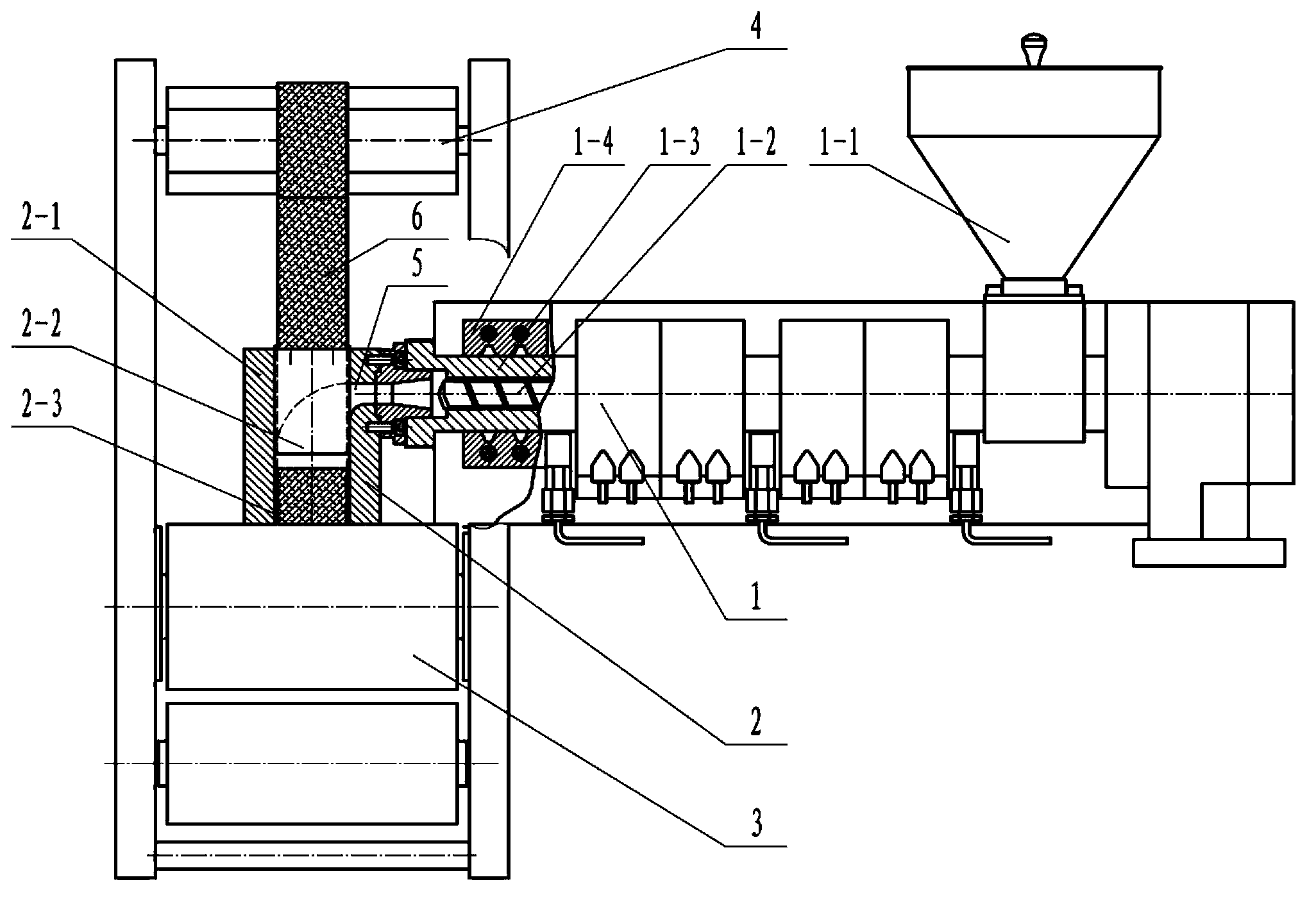
[0011] In view of the defects of long molding cycle, small product size and inability to produce continuously in the existing preparation method of single polymer composite material products, the purpose of the present invention is to provide a single polymer composite product melt coating roll forming method and Its equipment can be used for batch continuous molding to obtain large-sized single-polymer composite products with low density, high recycling rate and good interface adhesion

Method used


Image

  • Fusion coating roll-forming method and device for homopolymer composite material
  • Fusion coating roll-forming method and device for homopolymer composite material
  • Fusion coating roll-forming method and device for homopolymer composite material

Examples


Embodiment 1

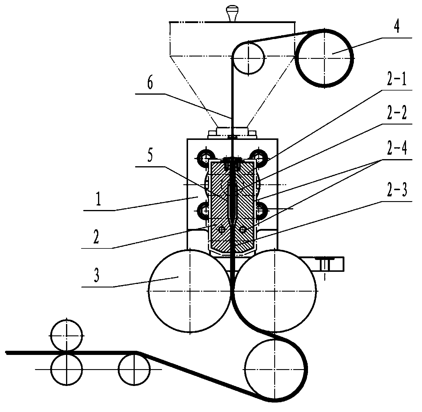
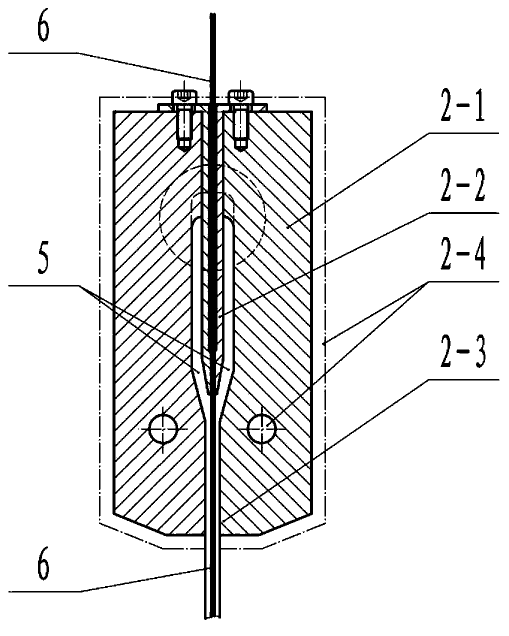
[0041] A single-polymer composite material product melt-coating roll forming equipment, the equipment is composed of an extruder (1), a machine head (2), a roller press (3) and a traction device (4), the extruder (1) It is mainly composed of hopper (1-1), screw (1-2), barrel (1-3), heating and cooling system I (1-4), and the machine head (2) is mainly composed of machine head body (2 -1), distribution pipe (2-2), die (2-3), heating and cooling system II (2-4), characterized in that: the outer wall or / and wall of the barrel (1-3) There is a heating and cooling system I (1-4), the screw (1-2) is inside the barrel (1-3), the hopper (1-1) is at the rear end of the barrel (1-3); the barrel ( 1-3) The front section is fixedly connected with the rear end of the machine head body (2-1), the shunt pipe (2-2) is set inside the machine head body (2-1), and the die (2-3) is set in the machine head body (2-1) front end, heating and cooling system II (2-4) is set in the outer wall or / and w...

Embodiment 2

[0051] The difference from Example 1 is that the machine head (2) is designed according to a plate product with a thickness of 6 mm and a width of 40 mm; the shunt pipe (2-2) has three tube holes, all of which are rectangular holes with a length of 38 mm and a width of 1 mm. The reinforcement adopts three layers of fiber tapes with a thickness of 1mm and a width of 38mm, which can pass through the three pipe holes of the middle shunt pipe (2-2) through traction; the outlet hole of the die (2-3) is 40mm long and 7mm wide The two rollers of the roller press (3) are set at the front end of the die (2-3), and the gap between the two rollers is 6mm, so that a single polymer compound with a thickness of 6mm and a width of 40mm can be finally formed. Material sheet products.


PUM

PropertyMeasurementUnit
melting pointaaaaaaaaaa

Abstract

The invention relates to a fusion coating roll-forming method and a fusion coating roll-forming device for a homopolymer composite material, belonging to the technical field of forming processing of polymer composite materials. The fusion coating roll-forming method comprises the following steps of: forwards conveying a base body at a fusion state under the action of an extruding pressure and cooling the base body with the fusion state to a base body with an overcooling state, coating a reinforcement after distribution, and then roll-compounding to obtain the homopolymer composite material. The homopolymer composite material prepared by adopting the method is large in size and is capable of realizing continuous volume production. The fusion coating roll-forming device comprises an extruder, a nose, a roller press and a traction device. The fusion coating roll-forming device is simple in structure and easy to operate, and can be used for roll-forming the homopolymer composite material with small density, high recycling utilization and good interface adhering property through fusion coating.

Description

technical field [0001] The invention relates to a single-polymer composite material product melting coating roll forming method and equipment, and belongs to the technical field of polymer composite material forming and processing. Background technique [0002] Traditional fiber-reinforced polymer composites are composed of a matrix and a reinforcement. Polymers such as polypropylene and polyethylene are usually used as the matrix, and glass fibers, carbon fibers, boron fibers, aramid fibers, and silicon carbide fibers are used as reinforcements. For example, glass fiber-reinforced polypropylene composite material is a fiber-reinforced polymer composite material with polypropylene as the matrix and glass fiber as the reinforcement. It has a great application rate especially in the "plastic strip steel" of automobiles. However, due to the different materials used for the matrix and reinforcement, the recycling of traditional fiber-reinforced polymer composites is severely lim...

Claims


Application Information

Patent Timeline
Patent Type & Authority Applications(China)
IPC IPC(8): B29C47/02B29C47/04B29C47/80
Inventor 王建陈晋南彭炯
Owner BEIJING INSTITUTE OF TECHNOLOGYGY
Learn More