Cooling block for polycrystalline silicon ingot furnace

A polycrystalline silicon ingot furnace and cooling block technology, which is applied to the growth of polycrystalline materials, crystal growth, single crystal growth, etc., can solve the problems of inability to suppress preferential crystallization, grain growth direction deviation, low photoelectric conversion efficiency, etc. The effect of inhibiting preferential growth, improving quality, and improving photoelectric conversion efficiency

Active Publication Date: 2013-10-23
浙江省机电设计研究院有限公司
View PDF6 Cites 5 Cited by
  • Summary
  • Abstract
  • Description
  • Claims
  • Application Information

AI Technical Summary

Problems solved by technology

The invention patent includes a furnace body and a bracket. There is a crucible in the furnace body, a graphite crucible on the outside of the crucible, and a graphite cooling block below the graphite crucible. Although this patent increases the effect of purification and crystal growth, it improves the reliability of the polysilicon ingot casting device. , but the heat dissipation at the bottom of the crucible is faster, the grain production speed near the crucible is faster, and the growth direction of the grain is shifted, so it still has the above defects
[0006] Chinese Patent No. 200820031102.X discloses a utility model patent titled "Polysilicon Ingot Furnace Thermal Field Structure with Graphite Cooling Block Insulation Bar", which includes a thermal insulation cage, and the thermal insulation cage is installed on the side With the heater on the top surface and the graphite cooling block where the crucible is placed, insulation strips are installed around the bottom of the graphite cooling block. This patent reduces the content of microcrystals in the effective area, but cannot inhibit the preferential crystallization near the crucible wall, and the photoelectric conversion efficiency is low. , so it still has the above defects

Method used


Image

  • Cooling block for polycrystalline silicon ingot furnace
  • Cooling block for polycrystalline silicon ingot furnace
  • Cooling block for polycrystalline silicon ingot furnace

Examples


Embodiment 1

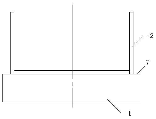
[0019] Embodiment one: see Figure 1-Figure 3 , This embodiment includes a cooling block body 1 , a crucible 2 , a groove 3 , an inner wall 4 , an outer wall 5 , a groove depth 6 and a top surface 7 .

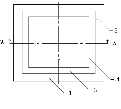
[0020] The cooling block body 1 in this embodiment is in contact with the crucible 2, the crucible 2 is located on the top surface of the cooling block body 1, the top surface 7 of the cooling block body 1 is provided with an annular square groove 3, and the center line of the groove 3 is in line with the The centerlines of the cooling block body 1 coincide with each other, and the crucible 2 is placed on the cooling block body 1 for directional solidification.

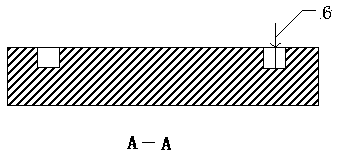
[0021] Groove 3 in this implementation comprises inner wall 4 and outer wall 5, and the inner wall 4 sides length of groove 3 is 625mm, and outer wall 5 sides length is 780mm, and the groove width of groove 3 is 103mm, and the groove depth 6 of groove 3 is 5mm , the sides of the inner wall 4 and the outer wall 5 of th...

Embodiment 2

[0025] Embodiment two: see Figure 1-Figure 3 , This embodiment includes a cooling block body 1, a crucible 2, a groove 3, an inner wall 4, an outer wall 5 and a groove depth 6.

[0026] In this embodiment, the cooling block body 1 is in contact with the crucible 2, the crucible 2 is located on the top surface of the cooling block body 1, the top surface 7 of the cooling block body 1 has a groove 3, and the cooling block body 1 is made of graphite.

[0027] In this embodiment, the centerline of the groove 3 is on the same straight line as the centerline of the cooling block body 1. The groove 3 includes an inner wall 4 and an outer wall 5. The groove 3 is an annular square. The inner wall 4 and the outer wall of the groove 3 The sides of 5 and the corresponding sides of the cooling block body 1 are parallel to each other.

[0028] In this embodiment, the inner wall 4 of the groove 3 has a length of 677 mm, the outer wall 5 has a side length of 875 mm, the groove width of the ...

Embodiment 3

[0031] Embodiment three: see Figure 1-Figure 3 , This embodiment includes a cooling block body 1, a crucible 2, a groove 3, an inner wall 4, an outer wall 5 and a groove depth 6.

[0032] In this embodiment, the cooling block body 1 is in contact with the crucible 2, the crucible 2 is located on the top surface of the cooling block body 1, the top surface 7 of the cooling block body 1 has a groove 3, and the cooling block body 1 is made of graphite.

[0033] In this embodiment, the centerline of the groove 3 and the centerline of the cooling block body 1 are on the same straight line, the groove 3 includes 4 and the outer wall 5, and the four sides of the groove 3 correspond to the four sides of the cooling block body 1 in the corresponding direction Parallel to each other, the groove 3 is an annular square.

[0034] In this embodiment, the 4 sides of the inner wall of the groove 3 are 780 mm long, the 5 sides of the outer wall are 935 mm long, the groove width of the groove...


PUM

PropertyMeasurementUnit
widthaaaaaaaaaa
depthaaaaaaaaaa
depthaaaaaaaaaa

Abstract

The invention relates to a cooling block for a polycrystalline silicon ingot furnace, and belongs to the fields of novel energy and photovoltaics. The cooling block comprises a cooling block body and a crucible, the crucible is disposed at the top surface of the cooling block body; the top surface of the cooling block body is provided with a groove; the crucible covers on the groove; and the central line of the groove, the central line of the crucible and the central line of the cooling block overlap with one another. Proper heat preservation for corner parts of the crucible by arranging a square groove and utilizing difference between thermal conductivities of the air and graphite, so that preferential growth of crystal grains near the wall of the crucible is inhibited; relatively flat solid-liquid interface can be obtained; and the quality of directionally solidified polycrystalline silicon can be increased.

Description

technical field [0001] The invention relates to a cooling block, in particular to a polycrystalline silicon ingot furnace cooling block, which is mainly used in the thermal field system of polycrystalline silicon directional solidification casting equipment in the field of photovoltaic solar energy, and belongs to the fields of new energy and photovoltaics. Background technique [0002] In recent years, with the depletion of fossil and non-renewable resources such as petroleum and coal in the world, solar energy has gradually become one of the most important renewable new energy sources in the future. Polycrystalline silicon solar cells are one of the most important photovoltaic products. The preparation of this product requires The solar grade silicon material is cast into silicon ingots, and then squared, sliced ​​and other steps are made to make silicon wafers for solar cells, and then the subsequent production of solar cells, modules, and power stations is carried out. ...

Claims


Application Information

Patent Timeline
Patent Type & Authority Applications(China)
IPC IPC(8): C30B11/00C30B28/06C30B29/06
Inventor 沈永华黄列群潘东杰夏小江高强汤瑶朱丹
Owner 浙江省机电设计研究院有限公司
Why Eureka
Try Eureka