Supercharge Your Innovation With Domain-Expert AI Agents!

Oil drainer for sand control valve

A technology for oil drainage and sand control, applied in the fields of production fluids, wellbore/well components, earthwork drilling, etc., can solve the problems of increasing installation and maintenance workload, etc., and achieve the effect of protecting the environment, ensuring safe operation, and preventing scratches

Inactive Publication Date: 2013-10-23
杨二龙
View PDF0 Cites 0 Cited by
  • Summary
  • Abstract
  • Description
  • Claims
  • Application Information

AI Technical Summary

Problems solved by technology

In addition, the traditional oil pump needs to install the oil drain mechanism separately, which increases the workload of installation and maintenance.

Method used


Image

  • Oil drainer for sand control valve

Examples


Embodiment Construction

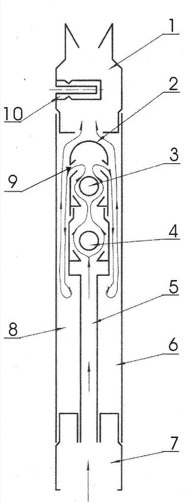
[0011] Combine below figure 1 The present invention is further described:

[0012] When the oil enters the center pipe 5 of the device through the lower joint 7 after the traditional sand removal, the lower ball 3 and the upper ball 4 are pushed away successively under the pressure of the oil flow. It enters into the annular cavity 8 through the downwardly sloped discharge hole 9 provided on the upper ball valve cover 2 . Due to the expansion of the space, the discharged oil immediately diffuses, the flow rate becomes slow, and the buoyancy decreases. The sand and other sundries in the oil that slipped through the first sand control pipe sink into the lower part of the annular cavity of the device. , no longer enters the oil well pump with the oil flow, and the clean oil enters the oil well pump through the upper joint 1 after precipitation.

[0013] When the pump needs to be lifted, the sucker rod and the plunger in the pump are first put out, and then a short rod is put in...


PUM


Abstract

The invention belongs to the technical field of oil production equipment and relates to an oil drainer for a stand control valve. The oil drainer is characterized in that a central tube is disposed in a body outer tube, a circular cavity is formed between the body outer tube and the central tube, and two sets of valves and seats are further disposed in the body outer tube. After oil is subjected to sand removal by a traditional sand control tube at the lower end, space is larger, the oil discharged in spreads immediately and flows slowly with less buoyancy, impurities such as sand filtered from the oil by a strainer in the sand control tube sink down to the bottom the circular cavity of the oil drainer. A hollow blind-hole shear pin is added to the upper portion of the oil drainer; when pump lifting is required, residual oil in a tubular pile automatically flows back into a well from a central hole of the broken hollow blind-hole shear pin by punching off the hollow blind-hole shear pin.

Description

technical field [0001] The invention belongs to the technical field of oil extraction equipment, and relates to a sand prevention valve oil drainage device. Background technique [0002] At present, in domestic mechanical oil recovery, the downhole main engine is an oil well pump. In order to ensure the normal operation of the oil well pump, the sand particles and various sundries contained in the oil should be removed, and filtered into a clean oil to enter the pump. The traditional oil pump sand control process is to install sand control pipes with various structures under the fixed valve assembly under the oil well pump, which becomes a sand control line. However, there are often a small number of sundries such as sand that slip through the net and cannot be filtered clean. After entering the tubular oil well pump, it will cause scratches and wear to the inner wall of the pump chamber and the plunger. For this reason, sand control can no longer meet the needs of sand cl...

Claims


Application Information

Patent Timeline
Patent Type & Authority Applications(China)
IPC IPC(8): E21B43/12E21B43/02
Inventor 杨二龙季会军高玉森
Owner 杨二龙
Features
  • R&D
  • Intellectual Property
  • Life Sciences
  • Materials
  • Tech Scout
  • Unparalleled Data Quality
  • Higher Quality Content
  • 60% Fewer Hallucinations
Learn More