
Low temperature electric precipitation system in fuel electric plant

A thermal power plant, low and low temperature technology, which is applied in the field of low and low temperature electrostatic precipitator systems in thermal power plants to achieve the effects of saving equipment investment, improving thermal economy, and reducing the power consumption rate of the plant

Inactive Publication Date: 2013-10-23
ZHEJIANG ELECTRIC POWER DESIGN INST +1
View PDF7 Cites 24 Cited by
  • Summary
  • Abstract
  • Description
  • Claims
  • Application Information

AI Technical Summary

Problems solved by technology

With the implementation of the latest version of "Emission Standards of Air Pollutants for Thermal Power Plants", it is required that the emission concentration of smoke and dust be controlled below 30mg / Nm??, and the special emission limit of smoke and dust in key areas is even below 20mg / Nm??. Dust removal technology presents new challenges

Method used


Image

  • Low temperature electric precipitation system in fuel electric plant
  • Low temperature electric precipitation system in fuel electric plant

Examples


Embodiment

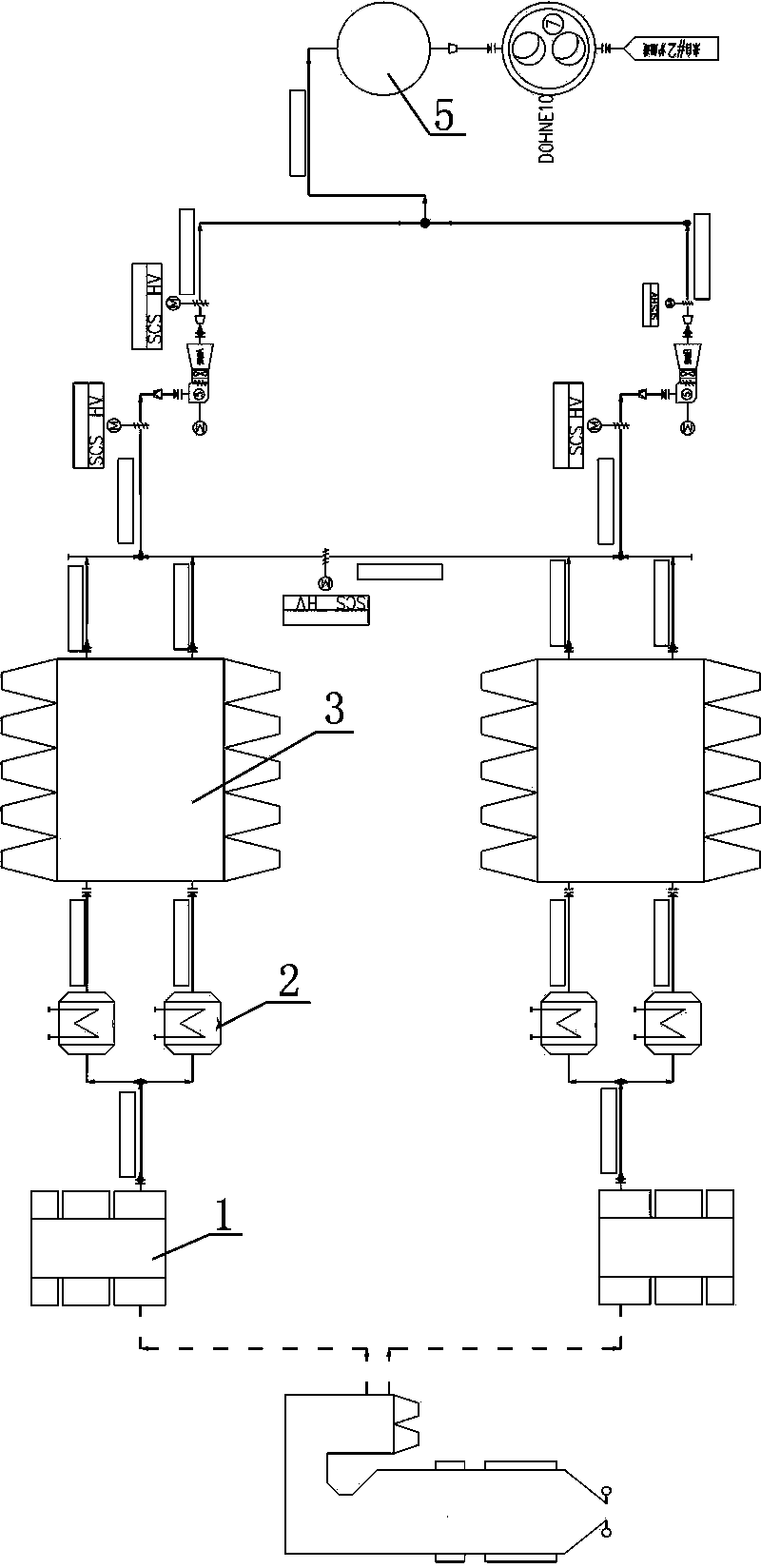
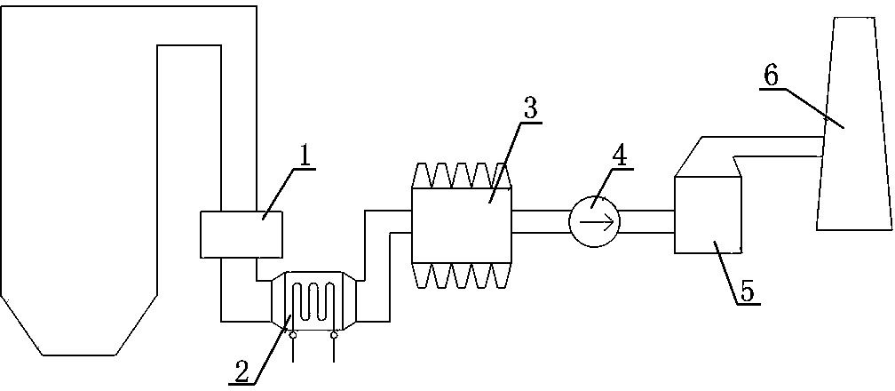
[0020] figure 1 , 2 As shown, the present invention includes a connecting pipe connecting the air preheater 1 and the electrostatic precipitator 3 and a flue gas heat exchanger 2 between the two devices, and the induced draft fan 4 is arranged on the electric precipitator 3 and the desulfurization absorption tower 5 through the connecting pipe Between, the chimney 6 is arranged after the desulfurization absorption tower 5.

[0021] The flue gas temperature at the inlet of the flue gas heat exchanger 2 is 120°C, and the flue gas temperature at the outlet is 90°C, which is lower than the dew point temperature of the flue gas; all the condensed water from the outlet of the 7# low-pressure heater flows to the flue gas heat exchanger 2, and condenses The water is heated from 70°C to 87°C in the flue gas heat exchanger 2 and then returns to the inlet of the 6# low-pressure heater. The heat exchange type of the flue gas heat exchanger 2 can adopt countercurrent heat exchange. The h...


PUM


Abstract

A low temperature electric precipitation system in a fuel electric plant comprises at least one air preheater, at least one electric precipitator and connecting pipes for connecting the air preheater and the electric precipitator together, a flue-gas heat exchanger for lowering the flue-gas temperature entering the electric precipitator to enable the flue-gas temperature to reach or be lower than flue-gas dew point at the temperature of 90 DEG C is arranged between the air preheater outlet and the electric precipitator inlet; the electric precipitator is communicated with a desulfuration absorption tower through an induced-draft fan; a chimney is connected with the rear part of the desulfuration absorption tower. The flue-gas heat exchanger adopts a backward flow heat exchange type; a vertical pipe heat exchange flow passage or a horizontal pipe heat exchange flow passage is arranged at the inner part of the flue-gas heat exchanger; the system has the characteristics that the project equipment investment is reduced; the auxiliary power ratio is lowered; the energy is saved; the consumption is reduced; the heat economy of the unit can be improved; the latest environment-friendly emission standard can be satisfied.

Description

technical field [0001] The invention relates to a low-temperature electric dust removal system of a thermal power plant, belonging to the technical field of thermal power plant design. Background technique [0002] Most of the flue gas heat exchangers in thermal power plants are arranged after the electrostatic precipitator, and some projects are arranged in front of the electrostatic precipitator, but the schemes arranged in front of the electrostatic precipitator are mostly used in renovation projects, and the flue gas entering the electrostatic precipitator The temperature is higher than the flue gas dew point temperature. The purpose of installing the flue gas heat exchanger is to use the waste heat at the tail of the boiler to heat the condensate water of the turbine to improve the thermal economy of the unit, or to heat the desulfurized clean flue gas to increase the temperature of the chimney exhaust gas. However, the arrangement of the flue gas heat exchanger behind...

Claims


Application Information

Patent Timeline
Patent Type & Authority Applications(China)
IPC IPC(8): F23J15/00
Inventor 张加权胡蓉卞卡程慧张卫灵沈又幸李琪卢婉珍解永刚许明磊
Owner ZHEJIANG ELECTRIC POWER DESIGN INST
Learn More