Method of cutting ingot by wire-cutting mesh

A technology of splitting nets and ingots, which is applied in the direction of fine working devices, stone processing equipment, manufacturing tools, etc., can solve the problems of affecting work efficiency, reducing production capacity, and unstable tension, so as to improve production efficiency and production capacity, improve The effect of reducing product yield and disconnection

Inactive Publication Date: 2013-10-30
HENGSHUI YINGLI NEW ENERGY
View PDF6 Cites 7 Cited by
  • Summary
  • Abstract
  • Description
  • Claims
  • Application Information

AI Technical Summary

Problems solved by technology

However, due to the position of the pulley and its own characteristics, there are many problems in the slicing process, which seriously affects the pass rate and production capacity of the product.
[0004] 1) When performing wire mesh operation, it is necessary to adjust the direction and position of the pulleys on both sides of the guide wheel by visual inspection. Due to the deviation in visual inspection, if the deviation is large, it will cause the steel wire to jump out of the groove of the guide wheel, which will cause skewing , resulting in a large number of defective silicon wafers
[0005] 2) Since the material of the pulley jacket installed on the pulley is rubber, and the groove is V-shaped, the steel wire travels in the pulley jacket, which will cause the pulley jacket to wear, for example, the steel wire is broken due to deep or partial cutting of the pulley jacket
Disconnection will cause the wire network to be evacuated, and the ingots in this evacuated area cannot be sliced, which will affect the yield of silicon wafers
At the same time, it takes a certain amount of time to deal with disconnection, which affects work efficiency.
[0006] 3) The pulley will shake after being used for a certain period of time. If the steel wire continues to run around the pulley, the steel wire will have a large jump and the tension will be unstable, which will produce more unqualified pieces and affect the cutting quality
[0007] 4) Due to the position of the pulley in the cutting room and the structure of the pulley itself, the pulley can only move within a certain area. If the length of the silicon block in front of the wire mesh is too long, the pulley cannot reach the designated position for wire mesh operation. The second silicon block cannot be bonded behind one silicon block. In this way, the cutting length of the whole saw is shortened, and the cutting is completed within the same time, which will inevitably reduce the production capacity.

Method used


Image

  • Method of cutting ingot by wire-cutting mesh
  • Method of cutting ingot by wire-cutting mesh

Examples


Embodiment 1

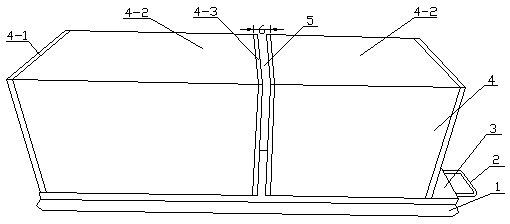
[0027] A method for cutting a crystal rod by a wire-dividing net, comprising the following steps (such as figure 1 shown):

[0028] 1) Band sawing process: the width of the bottom 4-1 of each silicon block 4 and the effective cutting length 4-2 of the silicon block are fixed values, and the top 4-3 of the two silicon blocks 4 are measured using a steel ruler , the area 4-1 at the bottom of the silicon block, and use a marker pen to mark the entry position of the band saw when cutting the silicon block, that is, the positions of the top 4-3 of the silicon block and the bottom 4-1 of the silicon block, each with a width of 2mm. Use Wuxi Shangji band saw machine tool for cutting (a band saw blade is installed on the band saw machine tool, the band saw blade rotates at high speed, the silicon block moves slowly with the worktable of the band saw machine tool, and the band saw blade cuts the silicon block).

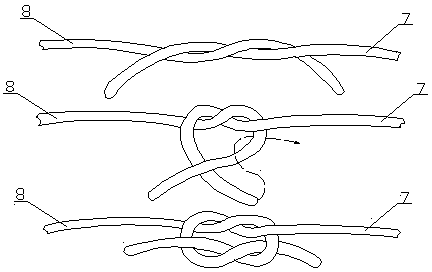
[0029] 2) Bonding process: Before slicing, a bonding process is required...

Embodiment 2

[0038] The difference from Example 1 is that in step 1), the top 4-3 of the silicon block and the bottom 4-1 of the silicon block each retain a width of 3 mm; in step 2), a gap 5 with a width of 5 mm is left between the two silicon blocks 4 . Using the method improves the qualified rate of products, production efficiency and production capacity.

Embodiment 3

[0040] The difference from Example 1 is that in step 1), the top 4-3 of the silicon block and the bottom 4-1 of the silicon block each retain a width of 2.5 mm; in step 2), a gap 5 with a width of 4 mm is reserved between the two silicon blocks 4 . Using the method improves the qualified rate of products, production efficiency and production capacity.


PUM


Abstract

The invention discloses a method of cutting an ingot by a wire-cutting mesh, and relates to the technical field of solar ingot cutting. The method includes 1, measuring the tops and bottoms of two silicon blocks, and marking cutting positions, namely 2 to 3mm widths reserved on the tops and bottoms of the two silicon blocks, when a machine with a saw cuts, and cutting; 2, bonding a tray and glass, then bonding the two silicon blocks, reserving a gap 3 to 5mm in width between the two silicon blocks, and finishing producing the ingot; 3, marking effective cutting lengths of the silicon blocks, then loading the ingot on a fret-saw machine, weaving a mesh on a guide wheel till extending 10mm length of a non-cutting area between the two silicon blocks, cutting the mesh in the non-cutting area between the two silicon blocks, tying knots, weaving the mesh continuously till finishing, and wrapping the knots on a winding shaft. By the aid of the method, the wire-cutting mesh can be operated without pulleys, product qualified rate can be increased, and production efficiency, operation rates and capacity can be improved greatly.

Description

technical field [0001] The invention relates to the technical field of solar crystal rod cutting. Background technique [0002] Solar crystal ingots are generally cut using a wire saw machine tool. The basic principle of the wire saw cutting technology is: a slender steel wire is wound around a number of guide wheels (the guide wheel is the wheel body responsible for winding in the wire saw machine tool, and the internal It is made of steel, and a layer of polyurethane is laid on the outside. Its rotation depends on the bearings at both ends and the screw passing through the middle). The groove of the guide wheel is fine and the groove distance is uniform, forming a horizontal network structure of parallel cutting steel wires. The guide wheel rotates rhythmically in one direction at high speed to realize the high-speed movement of the steel wire. The equipment is equipped with a mortar spraying system powered by a compression pump. The mortar is formulated with surfactant...

Claims


Application Information

Patent Timeline
Patent Type & Authority Applications(China)
IPC IPC(8): B28D5/04
Inventor 徐丽美刘凯马腾陶朋
Owner HENGSHUI YINGLI NEW ENERGY
Why Eureka
Try Eureka