Turntable sensor element with uneven distribution of multi-magnetic blocks

A technology of evenly distributed, sensing elements, applied in vehicle components, torque measurement, instruments, etc., can solve the problems of unstable motor operation, lack of power assistance, inconsistent power output and power demand, etc., to achieve low cost and structure. simple effect

Inactive Publication Date: 2016-07-06
湖南双创部落信息咨询服务有限责任公司
View PDF8 Cites 0 Cited by
  • Summary
  • Abstract
  • Description
  • Claims
  • Application Information

AI Technical Summary

Problems solved by technology

[0015] Disadvantages (1) Using two permanent magnets with no difference to represent the fixed positions of the two pedals, only multiple Halls can be used to represent the pedals Rotation position: There is no difference between the two permanent magnets. The advantage is that the fixed positions of the two pedals can be expressed regardless of the left and right feet, so that the left and right feet can generate power assistance requirements, which can produce the same motor power assistance effect; but the disadvantage is that The permanent magnetic steel itself cannot indicate the rotation position of the pedal, but can only use multiple Halls at different corner positions to indicate the rotation position of the pedal, so it is not possible to use only one Hall, but must use multiple Halls
[0016] Disadvantage (2) Only one Hall cannot be used, but three Halls will inevitably cause the original segmentation error of the three control signals, which will distort the power-assist demand model, naturally The generation of power output is inconsistent with the demand for power assistance: no matter whether the power-assisted bicycle has one or two motors, the sensor signal for controlling the motor can only be controlled by using one sensor signal input to the motor controller; and the patent uses three sensors. If Hall controls the motor, the three control signals of the three Halls must be combined into one combined control signal before it can be input to the motor controller
The sensing parameters of the three Halls cannot be the same, especially due to changes in ambient temperature and long-term use, the sensing parameters of the three Halls may vary greatly. The output voltages are different, resulting in different power output of the motor, and the power output is inconsistent with the power demand; similarly, when the power demand is the same, the outputs of different Halls may be the same voltage, resulting in the same power output of the motor, and also There is a problem that the power output is inconsistent with the power demand
[0017] Disadvantages (3) The combined control signal is prone to signal drift, which makes the combined control signal not match the motor controller, and the power-assisted demand model is distorted: due to changes in ambient temperature and use time After a long period of time, the sensing parameters of the three Halls may vary greatly, and the connection points of the three control signals of the three Halls will inevitably change, so the combined control signals generated by the same boosting demand will produce segmental signal drift. Combining the control signals as a whole produces signal distortion, that is, the power-assist demand model is distorted, causing the motor controller to choose any one of the three control signals as a reference, resulting in the inconsistency between the power-assisted output and the power-assisted demand
[0018] Disadvantages Sensing points cannot be increased arbitrarily, if there are too few sensing points, the operation of the motor will not be stable, making the rider feel very uncomfortable: due to the disadvantages (1) and disadvantage (2) are most caused by the number of Halls being greater than one. Obviously, the more the number of Halls, the more serious the disadvantages (1) and (2) are.
Therefore, the power-assisted bicycle provided by this patent can only be a very bad power-assisted bicycle that makes the rider feel comfortable.
[0019] Disadvantages (5) The signal blind area reaches 42 degrees, and when the power is needed when starting, it is impossible to get it: as we all know, the torque of the bicycle pedal is the smallest at the apex , from the angle of 10-45 degrees away from the top is the area that needs the most assistance, but the angle between the Halls in this patent is 42.5-43.5 degrees, and there is no Hall in the area of ​​10-42 degrees away from the top of the pedal. There is no control signal, and the result is when the assist is most needed, but the motor of the assist bicycle cannot assist
[0020]In a word, this patent is a technical solution of using multiple Halls to control the booster mode, because only multiple Halls can be used to represent the rotation position of the pedal, and multiple Halls The multiple control signals of Hall must have original errors, and the combined control signals are prone to signal drift, which can cause distortion of the assist demand model, that is, the same assist demand at different times, but different assist effects; the more the number of Halls, the more More, the more serious the distortion of the power-assisted demand model is, the quantity is limited, and the less quantity of Hall causes the motor to run unsteadily, which makes the rider feel very uncomfortable and cannot get power-assisted when starting
To make it undistorted to help the demand model, and to ensure the smooth operation of the motor, there are always two issues. It is impossible to have both.
[0021] International Patent Application WO / 099 / 13558AI discloses a sensor used to control the rotation of the motor on the motor. Inserted into the depression of the rotating disk, the permanent magnet block is cylindrical, and a permanent magnet block can only enable Hall to obtain one kind of magnetic induction intensity, that is, a sensor has only one sensing model, and the controlled object cannot be adjusted at any time. control model

Method used


Image

  • Turntable sensor element with uneven distribution of multi-magnetic blocks
  • Turntable sensor element with uneven distribution of multi-magnetic blocks
  • Turntable sensor element with uneven distribution of multi-magnetic blocks

Examples


Embodiment 1

[0059] Embodiment 1. Rotary disk sensor element with uneven distribution of multi-magnetic blocks

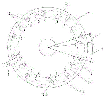
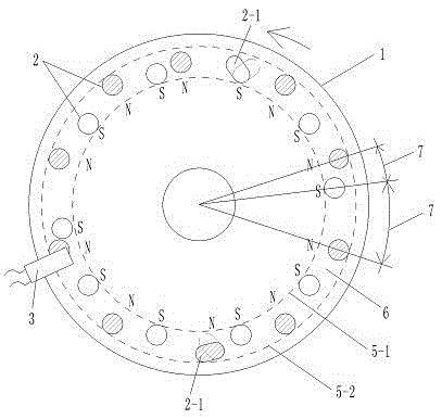
[0060] like figure 1 , 3 , 4, 5, one surface of a high-strength plastic rotating disk 1 with a diameter of 10.0 cm is provided with 20 permanent magnet blocks 2 with a diameter of 0.8 cm, and the magnetic flux is 146---279 (B·H)max / KJ·m -3 one of the values ​​in . The structure of rotating disk 1, permanent magnet block 2 and Hall 3 is as follows:

[0061] Each permanent magnet block 2 is fixed on the circular trajectory line 5-1 in the diameter of 8.5 centimeters, and within the circular ring 6 range between the outer circular trajectory line 5-2 of 9.5 centimeters, there are a plurality of permanent magnet blocks 2 into radius dislocations Distributed, there are a plurality of permanent magnet blocks 2 in dislocation distribution.

[0062] Radius dislocation distribution mode is: the plurality of permanent magnet blocks 2 are distributed within the scope of a circular rin...

Embodiment 2

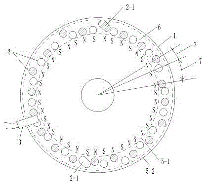
[0070] Embodiment 2. Rotary disk sensor element with uneven distribution of high-density magnetic blocks

[0071] like figure 2 , 3, 4, 5, one surface of a high-strength aluminum rotating disk 1 with a diameter of 10.0 cm is provided with 40 permanent magnet blocks 2 with a diameter of 0.6 cm. The magnetic flux of the permanent magnet block 2 is 146---279 (B·H)max / KJ·m -3 A certain value, Hall 3 keeps a distance of 0.2 cm from each permanent magnet 2 in the rotating state, so that when each rotating permanent magnet 2 passes through Hall 3, Hall 3 can generate a corresponding Square wave electrical signal output. The structures of other rotating disk 1, permanent magnet block 2, and Hall 3 are the same as those in embodiment 1.


PUM

PropertyMeasurementUnit
diameteraaaaaaaaaa
diameteraaaaaaaaaa
diameteraaaaaaaaaa

Abstract

The invention discloses a rotating disc type sensing element with a plurality of unevenly distributed magnet blocks, belongs to the technical field of providing signals through magnetic induction, and in particular relates to the technology of providing a control signal through multi-point position magnetic induction on a rotating part. A plurality of permanent magnets distributed annularly are fixedly arranged on a rotating disc, and the spacings between the plurality of permanent magnets are different; the adjacent permanent magnets are opposite in magnetic polarity on one surface of the rotating disc; in other words, the distribution manner of the magnetic polarities of all permanent magnets on one surface of the rotating disc are pole N, pole S, pole N...; and a hall is arranged in a position in the vicinity of the permanent magnets. The rotating disc type sensing element with the plurality of unevenly distributed magnet blocks has the following advantages that with the opposite N-S distribution manner of the magnetic polarities of the adjacent permanent magnets, the hall is capable of obtaining a rectangular wave signal, thereby facilitating digital processing of the signal; and as the spacings between the plurality of permanent magnets are different, the rectangular wave signal is capable of indicating the positions of the permanent magnets on the rotating disc; and therefore, the uses of different rectangular waves are determined.

Description

technical field [0001] The invention belongs to the technical field of providing signals by magnetic induction, and in particular relates to the technology of providing control signals by multi-point magnetic induction on a rotating component. Background technique [0002] The Chinese patent 201020295192.0 "Claw Type Torque Sensing Device" applied by Yebao Vehicle Material Industry (Kunshan) Co., Ltd. discloses a sensing device for power-assisted bicycles. The sensing device includes a magnetic part and an elastic part to sense the torque. sensing device. After a long time of use, the change of the elastic coefficient of the elastic member will lead to changes in the sensing signal and the control effect of the controlled motor, and the power-assisted effect will not match the power-assisted needs of people. Moreover, the design structure of the elastic member is complex and the manufacturing cost is high. [0003] The Chinese patent 01201843.0 "Automatic Detection Device ...

Claims


Application Information

Patent Timeline
Patent Type & Authority Patents(China)
IPC IPC(8): B62M6/50G01L3/00G01P3/481
Inventor 黄强
Owner 湖南双创部落信息咨询服务有限责任公司
Why Eureka
Try Eureka