Optical fiber ringdown cavity sensor array device based on wavelength division multiplexing

A technology of wavelength division multiplexing and sensor array, applied in the field of sensor network system, can solve the problems of resource waste and high cost, and achieve the effect of reducing cost

Active Publication Date: 2013-11-13
HEILONGJIANG UNIV
View PDF4 Cites 5 Cited by
  • Summary
  • Abstract
  • Description
  • Claims
  • Application Information

AI Technical Summary

Problems solved by technology

[0005] The purpose of the present invention is to solve the problem of high cost and waste of resources caused by each optical fiber ring-down cavity sensor corresponding to a light source and demo

Method used


Image

  • Optical fiber ringdown cavity sensor array device based on wavelength division multiplexing
  • Optical fiber ringdown cavity sensor array device based on wavelength division multiplexing
  • Optical fiber ringdown cavity sensor array device based on wavelength division multiplexing

Examples


specific Embodiment approach 1

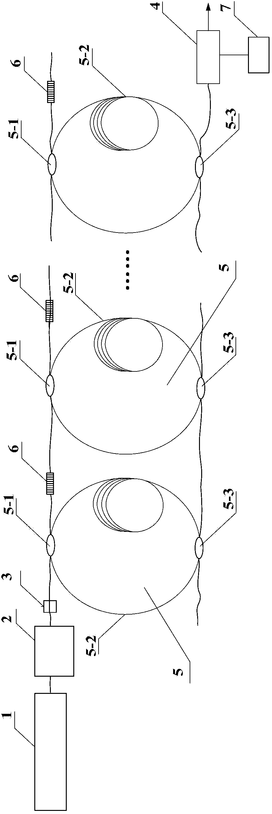
[0009] Specific implementation mode one: combine figure 1 Describe this embodiment mode, the optical fiber ring-down cavity sensor array device based on wavelength division multiplexing described in this embodiment mode, it includes a tunable laser 1, an acousto-optic modulator 2, an isolator 3, a photodetector 4, and a detection unit 7 , M optical fiber ring-down cavity sensors 5 and M fiber gratings 6, M is an integer greater than 1, the tunable laser 1, the acousto-optic modulator 2 and the isolator 3 are sequentially connected in the optical path, the optical fiber ring-down cavity sensor 5 Including an input coupler 5-1, an optical fiber 5-2 and an output coupler 5-3, the input coupler 5-1 and the output coupler 5-3 are connected by an optical fiber 5-2 to form a ring closed cavity structure, an optical fiber The input coupler 5-1 of the ring-down cavity sensor 5 is correspondingly connected with a fiber grating 6 through an optical fiber to form a group, and the signal l...

specific Embodiment approach 2

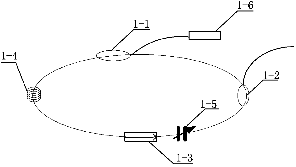
[0017] Specific implementation mode two: combination figure 2 This embodiment is described. This embodiment is for the tunable laser 1 of the optical fiber ring-down cavity sensor array device based on wavelength division multiplexing described in the first embodiment. The following structure can be used, which includes wavelength division multiplexer 1-1, 80:20 coupler 1-2, isolator 1-3, erbium-doped fiber 1-4, F-P filter 1-5 and semiconductor laser 1-6 , wavelength division multiplexer 1-1, erbium-doped optical fiber 1-4, isolator 1-3, F-P filter 1-5 and 80:20 coupler 1-2 are sequentially connected in series in the closed-loop optical path through the optical fiber, and the semiconductor laser The optical output end of 1-6 is connected with the optical input end of wavelength division multiplexer 1-1, and the 20% signal output end of 80:20 coupler 1-2 is the output end of tunable laser 1.

[0018] The tunable laser 1 provides a sweeping function in the wavelength division ...

specific Embodiment approach 3

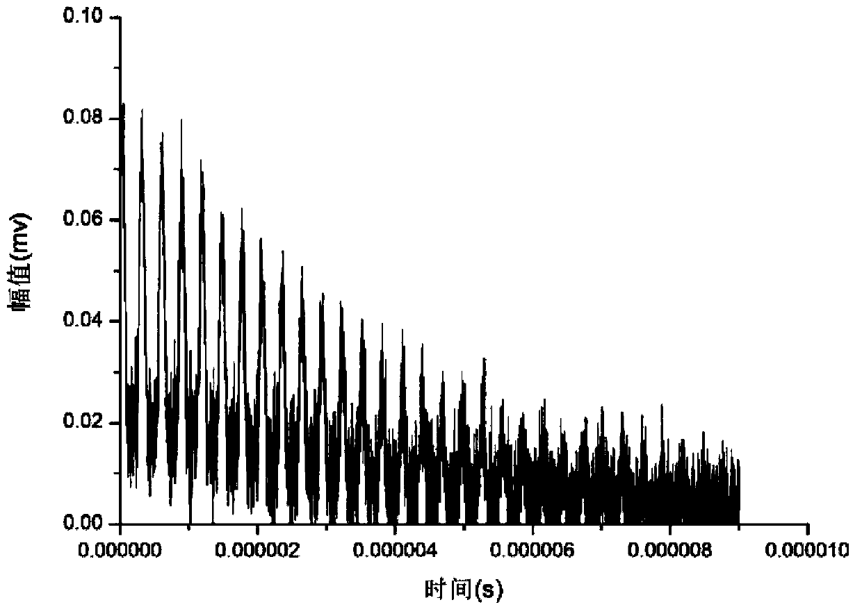
[0021] Specific implementation mode three: Using the principle of the optical fiber ring down ring, we designed a multiplexing sensor array structure with four ring down cavities. When the fiber ring down cavity length is selected as 60m, the ringdown time satisfies the following formula: Among them, the loss of one circle of the optical fiber ring cavity should satisfy: A=αL+E+γ, considering that the scattering loss is generally very small, and the scattering loss γ=0, that is to say, there will be such a formula: A=αL+E, where L= 60m, at the same time α=0.34dB / km, the insertion loss of the coupler is assumed to be 0.09dB, the loss of the fiber connection point is 0.02dB, and finally: E=2×0.09+3×0.02dB=0.24dB. so that =0.0599, (the introduction of 4.343 is to convert dB into 1 as the unit of data process dB=10 / ln10). which is: out of t 0 =4.88μs. Among them, the refractive index of single-mode fiber is n=1.464. At the same time, the time for light to travel a circle ...


PUM


Abstract

The invention relates to an optical fiber ringdown cavity sensor array device based on wavelength division multiplexing, relates to a sensor networking system, and aims to solve problems of high cost and resource waste due to the fact that a plurality of optical fiber ringdown cavity sensors are required in the physical quantity measurement of a plurality of positions, and each optical fiber ringdown cavity sensor correspondingly requires a light source and a demodulation light path. The device comprises a tunable laser, an acoustic-optical modulator, an isolator, a photoelectric detector, M optical fiber ringdown cavity sensors and M fiber bragg gratings, wherein the tunable laser, the acoustic-optical modulator and the isolator are sequentially connected to a light path in series; couplers of the M optical fiber ringdown cavity sensors and the fiber bragg gratings are sequentially connected in a light path in series through optical fibers, and the isolator is communicated with an input end of the light path; and output couplers of the M optical fiber ringdown cavity sensors are sequentially connected in an output light path in series through optical fibers, a light signal in the output light path is received by the photoelectric detector, and the photoelectric detector outputs a sensing signal. The optical fiber ringdown cavity sensor array device is applicable to sensor networking.

Description

technical field [0001] The invention belongs to the technical field of optical fiber sensing and measurement, and relates to a sensor network system. Background technique [0002] After the optical cavity ringdown (ringdown) technology was proposed in the 1980s, it has been widely studied and used, especially in the application of micro-variation measurement. The rapid development of optoelectronic technology and optical communication technology has promoted the wider application of optical fiber-based sensors. Therefore, in 2001, G.Stewart et al. first proposed the optical fiber ring ring-down cavity system and used it for stress, pressure and trace gases etc. [0003] Due to the excellent characteristics of optical fiber sensors such as low price, light weight, acid and alkali resistance, corrosion resistance and anti-electromagnetic interference, ring-down sensors based on optical fiber structures have received extensive attention. This technology is also called optical...

Claims


Application Information

Patent Timeline
IPC IPC(8): G01D5/38
Inventor 刘盛春李若明张金涛张云龙李坤
Owner HEILONGJIANG UNIV
Why Eureka
Try Eureka