Microwave power testing device based on universal serial bus (USB) interface

A USB interface, microwave power technology, applied in the field of microwave power test devices, can solve the problems of inconvenient portability, cumbersome program-controlled connection, cumbersome connection, etc., and achieves the effect of no calibration operation, easy system integration, and flexible programming.

Inactive Publication Date: 2013-11-13
THE 41ST INST OF CHINA ELECTRONICS TECH GRP
View PDF3 Cites 11 Cited by
  • Summary
  • Abstract
  • Description
  • Claims
  • Application Information

AI Technical Summary

Problems solved by technology

Due to the large size of the power test host, it needs to occupy a large space in the cabinet when building the test system, and generally requires 220V power supply, and requires program-controlled interfaces such as GPIB, serial port, or network port. The connection is cumbersome and inconvenient to carry, so generally It is limited to laboratory use, not suitable for on-site debugging, monitoring and production line use; and when multiple adjacent power ports need to be tested, multiple power meter hosts, cables and power probes need to be used at the same time, which takes up more space. Program-controlled connections are more cumbersome and costly
[0004] Therefore, in terms of system setup, on-site testing, production line testing, multi-channel testing, etc., there are many inconveniences in the existing microwave power testing device with desktop structure.

Method used


Image

  • Microwave power testing device based on universal serial bus (USB) interface
  • Microwave power testing device based on universal serial bus (USB) interface
  • Microwave power testing device based on universal serial bus (USB) interface

Examples


Embodiment Construction

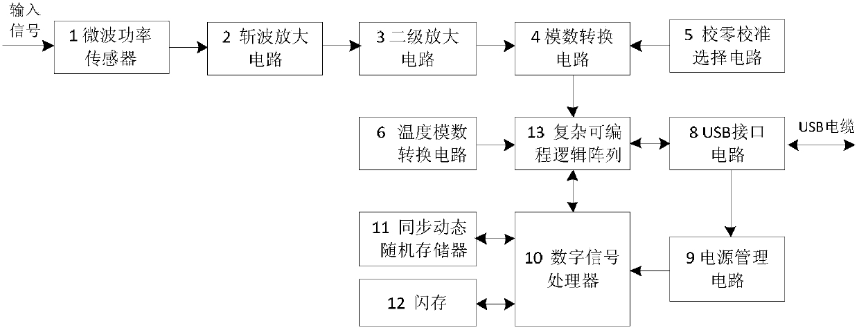
[0042] like figure 1 As shown, the microwave power test device based on the USB interface of the present invention includes: a microwave power sensor (1), an analog circuit board and a digital circuit board; wherein the analog circuit board and the digital circuit board are connected together through a high-density connector, and are connected by screws Fixed to the circuit board bracket, the housing and the microwave power sensor (1) are fixed to the bracket.

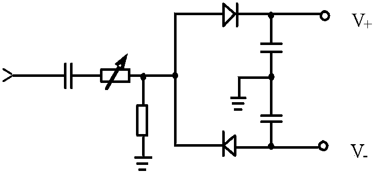
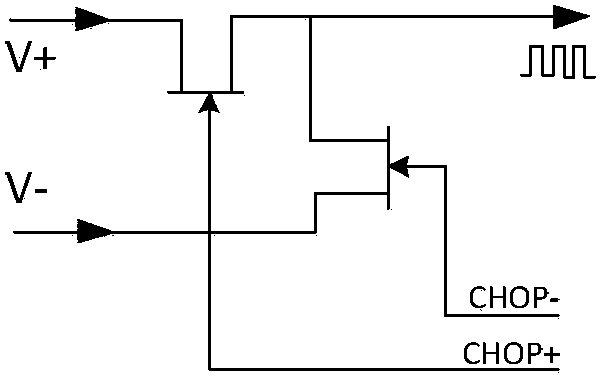
[0043] The analog circuit board includes a chopper amplifier circuit (2), a post-stage amplifier circuit (3), an analog-to-digital conversion circuit (4), a zero calibration selection circuit (5) and a temperature analog-to-digital conversion circuit (6).

[0044]The digital circuit board includes a digital signal processing circuit (7), a USB interface circuit (8) and a power management circuit (9).

[0045] The digital signal processing circuit (7) includes a digital signal processor (10), a synchronous dynamic data...


PUM


Abstract

The invention discloses a microwave power testing device based on a universal serial bus (USB) interface. The microwave power testing device comprises a casing, a circuit board support, a microwave sensor, an analog circuit board and a digital circuit board, wherein the analog circuit board and the digital circuit board are connected through a high-density connector, the analog circuit board comprises a chopping amplifying circuit, a rear-stage amplifying circuit, an analog-to-digital converting circuit, a zero calibration selection circuit and a temperature analog-to-digital converting circuit, the digital circuit board comprises a digital signal processing circuit, a USB interface circuit and a power source management circuit, and the digital signal processing circuit comprises a digital signal processor, a synchronous dynamic data storer, a flash memory program storage and a complicated programmable logic array chip. The microwave power testing device is compact in structure, small in size, light in weight and flexible in programming, adopts USB power supply, can be connected with computers with USB host interfaces or other electronic measuring instruments, can form a microwave power automatic testing system rapidly and is suitable for applications in places of laboratories, fields, production lines and the like.

Description

technical field [0001] The invention relates to a microwave power testing device, in particular to a microwave power testing device based on a USB interface. Background technique [0002] In the field of microwave power testing, the common microwave power testing device adopts the following test scheme: first, the microwave signal is converted into a weak DC voltage signal through the power probe, and after preliminary amplification, the analog signal is transmitted to the power meter through a multi-core cable The host, the power meter host performs post-stage amplification and filtering on the signal, converts it into a digital signal, and then completes the calibration and compensation of the signal by the DSP, and then reads the processed digital signal by the CPU (central processing unit) in the host, and directly through the display interface Displayed on the host screen, or interact with other control instruments through serial ports, GPIB (General Purpose Interface B...

Claims


Application Information

Patent Timeline
Patent Type & Authority Applications(China)
IPC IPC(8): G01R21/02
Inventor 赵浩徐达旺董占勇宁泽洪冷朋李金山李强
Owner THE 41ST INST OF CHINA ELECTRONICS TECH GRP
Why Eureka
Try Eureka