Vertical type oil separator

An oil separator and oil separation technology, used in refrigeration components, refrigerators, lighting and heating equipment, etc., can solve the problems of insufficient centrifugal force, affecting the oil separation effect, and worsening separation effect, and improve the volume and resistance of the cylinder. , The effect of the oil and gas separation process is sufficient and the gas velocity is reduced

Active Publication Date: 2013-11-20
GUANGDONG SHENLING ENVIRONMENT SYST CO LTD
View PDF7 Cites 3 Cited by
  • Summary
  • Abstract
  • Description
  • Claims
  • Application Information

AI Technical Summary

Problems solved by technology

In addition, in the practical process, the mixture of refrigeration oil and refrigerant gas is unevenly distributed when it enters and exits the oil separator, resulting in a high flow rate of the mixed gas in some areas, which affects the separation effect
[0005] Chinese Patent Publication No. CN101738034 discloses an invention patent application for "high-efficiency vertical oil separator device and its use method", which proposes a vertical oil separator combining centrifugal and fine filtration, but its centrifugal oil separation and The main operating space for filtering and separating oil overlaps, which makes the treatment process of oil-gas mixture shorter, which is not conducive to the separation of refrigerated oil as a whole, and the inlet of this oil separator is very close to the fine filter device, and the gas is easy to short circuit, resulting in the separation effect becomes worse, and when the load decreases and the gas flow rate decreases, the centrifugal force is obviously insufficient, resulting in the deterioration of the separation effect
The oil separator of this utility model adopts secondary oil separation, that is, filter oil separation and block oil separation, and the processing space of the secondary oil separation is staggered, that is, the filter device and the oil retaining devic

Method used


Image

  • Vertical type oil separator
  • Vertical type oil separator
  • Vertical type oil separator

Examples


Example Embodiment

[0029] The present invention will be further described below in conjunction with the accompanying drawings.
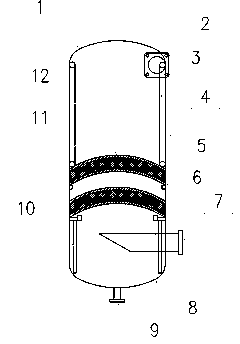
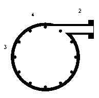
[0030] This embodiment is a horizontal oil separator applied to a large-scale flooded chiller. It consists of a cylinder 4, an upper head 1, a lower head 8, a fine filter element 10, an air inlet pipe 2, an air outlet pipe 7, an oil discharge pipe 8, and a spoiler 3. figure 1 The structure shown is installed. Among them, the two ends of the cylinder body 4 are welded with half standard elliptical heads 1 and 8 respectively to form a closed space; figure 2As shown, the intake pipe 2 enters along the tangential line from the upper part of the cylinder 4. The size of the intake pipe 2 is the same as that of the compressor exhaust pipe, so as to ensure a smooth transition of the flow channel, avoid extra noise and reduce resistance. The spoiler 3 can be directly welded on the cylinder wall to form a structure of a centrifugal oil separator together with the cylinder...


PUM


Abstract

The invention provides a vertical type oil separator which comprises a vertical type barrel (4), an air inlet pipe (2), an air outlet pipe (7) and an oil separation assembly. The air inlet pipe (2) is arranged at the upper end of the vertical type barrel (4), the air outlet pipe (7) is arranged at the lower end of the vertical type barrel (4), and therefore a stroke from top to bottom is formed inside the vertical type barrel (4). The oil separation assembly comprises a centrifugal oil separator body and a filtration type oil separator body, wherein the centrifugal oil separator body and the filtration type oil separator body are arranged in an up-and-down mode. According to the vertical type oil separator, the treatment process combining rotation centrifugal force with refined filtration is comprehensively utilized, the kinetic energy of gas is utilized fully, most large-diameter oil drops are removed under the condition that resistance is not augmented, the requirement for a fine filtration period is lowered, the oil-gas separation process is thorough, and the oil separation effect is improved under the condition that the size of the barrel and the resistance are not increased.

Description

technical field [0001] The invention belongs to the structural field of oil separators for air-conditioning and refrigeration system accessories, in particular to a vertical oil separator. Background technique [0002] In the refrigeration system, when the compressor is working, a small amount of refrigerated oil must be continuously pressed out together with the refrigerant and enter the pipeline of the refrigeration system, the condenser and the evaporator. When the refrigerating oil cannot be continuously returned to the compressor, the oil level of the compressor will drop, until the refrigerating oil is exhausted, and the compressor will burn due to lack of oil. Therefore, it is one of the most important issues in the design of the refrigeration system to ensure that the refrigerated oil is continuously returned to the compressor, and reducing the amount of refrigerated oil entering the system can improve the refrigeration efficiency of the unit and ensure the safe ...

Claims


Application Information

Patent Timeline
IPC IPC(8): F25B43/02
Inventor 张学伟李敏华潘展华陈华欧阳惕
Owner GUANGDONG SHENLING ENVIRONMENT SYST CO LTD
Why Eureka
Try Eureka