Array-type multi-optical-path system for gas-phase monitoring
An array type, multi-optical path technology, applied in the field of array type multi-optical path system, can solve problems such as complex manufacturing process, poor system stability, and unfavorable on-site testing, so as to increase the effective optical path length and avoid the trouble of coaxial adjustment , the effect of simple structure
- Summary
- Abstract
- Description
- Claims
- Application Information
AI Technical Summary
Problems solved by technology
Method used
Image
Examples
Embodiment 1
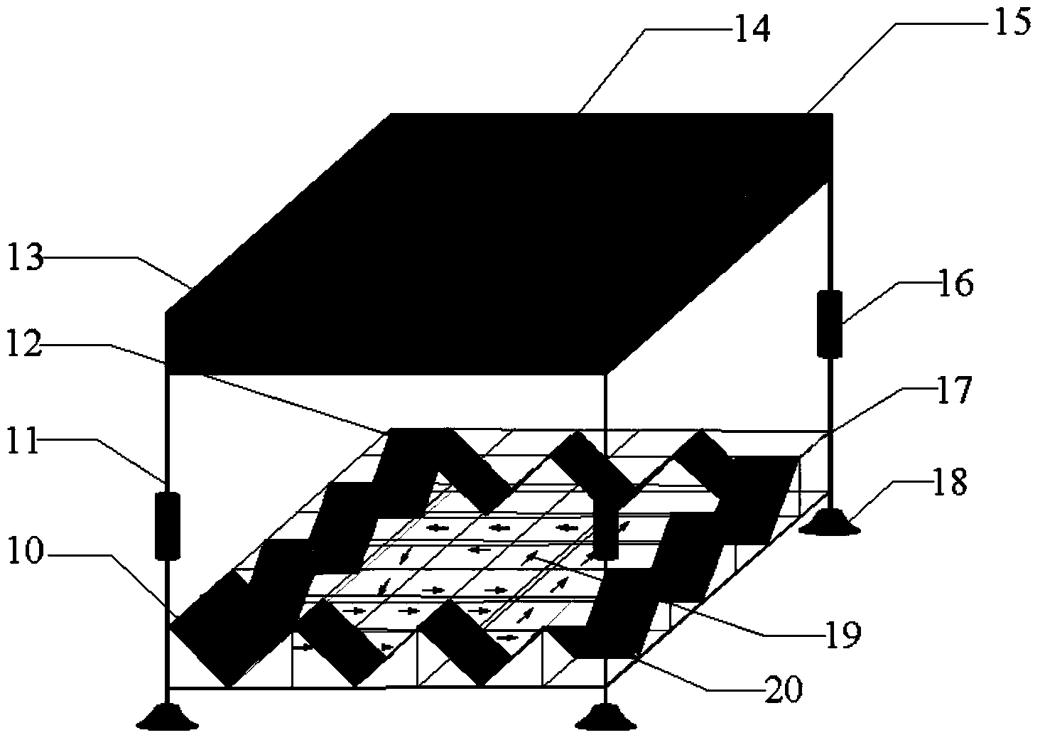
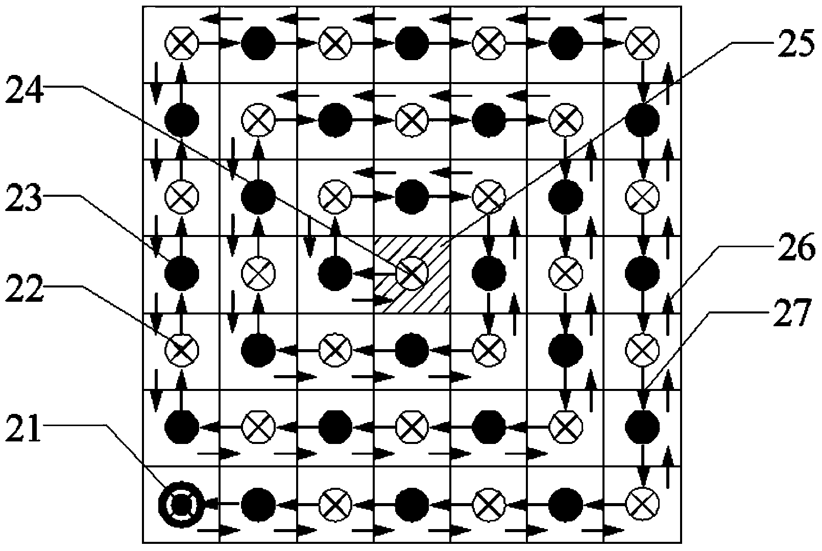
[0045] An arrayed multi-optical path system for gas phase monitoring comprises an arrayed multi-optical path absorption pool and a four-phase spectrometer, and the arrayed multi-optical path absorption pool is connected to the four-phase spectrometer by an optical fiber. The arrayed multi-path absorption cell is composed of multiple miniature plane mirrors, an open air chamber and an entrance hole. A plurality of miniature plane mirrors are arranged on the upper and lower surfaces of the open air chamber. The plane mirrors are arranged in an array and placed at an angle of π / 4 with the upper or lower surface. The last plane mirror is placed horizontally on the upper or lower surface. The lower surface; the upper surface of the open air chamber is provided with an incident hole for the incident light beam, and the incident hole is also an exit hole for the outgoing light beam. Open air chamber sides feature removable sealing panels with sealing grooves on each side. One of the...
Embodiment 2
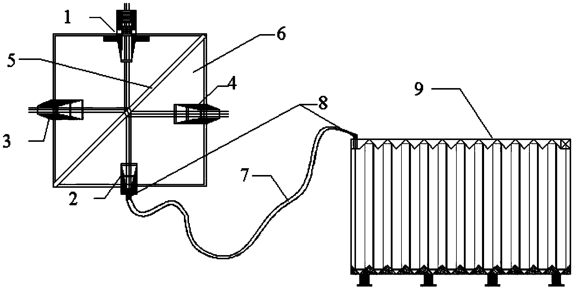
[0048] An array multi-light path system for gas phase monitoring includes a four-phase spectrometer and an optical long-range absorption cell. The four-phase spectrometer includes an incident light hole 1 , an exit light hole 2 , a photodetection receiving hole 3 , a photodetection receiving hole 4 and an optical fiber connector 8 . The incident laser light enters through the incident light hole 1, the projected light is reflected by the beam splitter 5 and enters the exit light hole 2, and the reflected light enters the photodetection receiving hole 3, and the detector installed in the photodetection receiving hole 3 receives the optical signal. The optical signal enters the optical fiber 7 from the exit light hole 2, and after a certain distance of transmission, enters the multi-optical path absorption cell 9 through the optical fiber joint 8. After being reflected in the absorption pool 9, the optical signal passes through the optical fiber connector 8, and the optical sign...
PUM
 Abstract
Description
Claims
Application Information
 - R&D
- Intellectual Property
- Life Sciences
- Materials
- Tech Scout
- Unparalleled Data Quality
- Higher Quality Content
- 60% Fewer Hallucinations
Browse by: Latest US Patents, China's latest patents, Technical Efficacy Thesaurus, Application Domain, Technology Topic, Popular Technical Reports.
© 2025 PatSnap. All rights reserved.Legal|Privacy policy|Modern Slavery Act Transparency Statement|Sitemap|About US| Contact US: help@patsnap.com


