
Shift register unit and driving method, gate driving circuit as well as display device thereof

A technology for shift registers and driving transistors, applied in static memory, digital memory information, instruments, etc., can solve the problems of large wiring area, transistor volume cannot be too large, complex structure, etc., and achieve reduced wiring area and compressed manufacturing cost , Enhance the effect of pull-down ability

Active Publication Date: 2013-11-20
BOE TECH GRP CO LTD +1
View PDF5 Cites 40 Cited by
  • Summary
  • Abstract
  • Description
  • Claims
  • Application Information

AI Technical Summary

Problems solved by technology

[0004] With the development of flat panel display technology, more and more attention has been paid to products with narrow bezels. However, the shift registers in the prior art usually use a large number of transistors and other electrical components, which not only have a complex structure, but also occupy a lot of space. The large wiring area is not conducive to the design of narrow borders. At the same time, it increases the difficulty of the manufacturing process of the shift register and increases the manufacturing cost.
Moreover, due to the limitation of the wiring space, the volume of the transistor should not be too large, which may cause the problem that the output signal cannot be pulled down to a low potential quickly and effectively due to the small size of the pull-down transistor.
At the same time, in the shift register unit in the prior art, since the control signal for the pull-up transistor is directly input to the pull-up transistor, this may affect the switch control of the pull-up transistor, resulting in the output signal of the shift register unit unstable

Method used


Image

  • Shift register unit and driving method, gate driving circuit as well as display device thereof
  • Shift register unit and driving method, gate driving circuit as well as display device thereof
  • Shift register unit and driving method, gate driving circuit as well as display device thereof

Examples


Embodiment 1

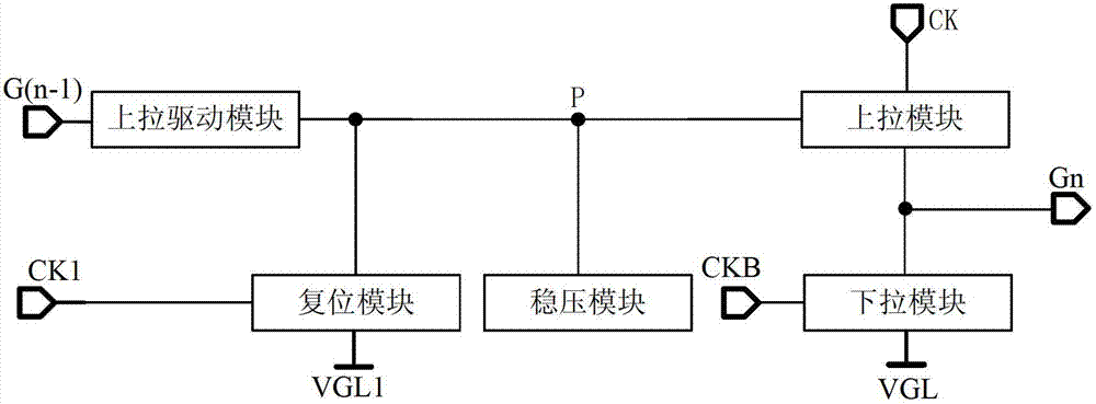
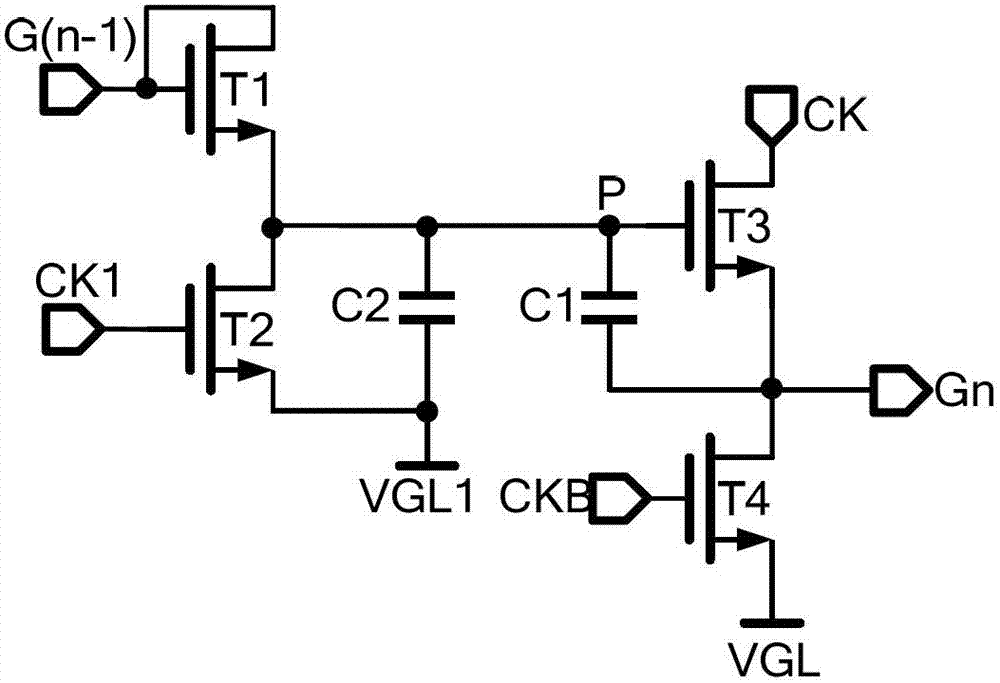
[0046] Such as figure 1 As shown in , a shift register unit provided in this embodiment mainly includes: a pull-up module, connected to the first clock signal input terminal, the signal output terminal and the pull-up node P respectively, for The potential at the point P outputs the signal input by the first clock signal input terminal to the signal output terminal; the pull-down module is connected with the signal output terminal, the first signal terminal and the second clock signal input terminal respectively, and is used to input the signal according to the second clock signal The potential of the signal output terminal pulls down the signal output terminal; the pull-up drive module is connected to the signal input terminal and the pull-up node P respectively, and is used to drive the pull-up module according to the signal input from the signal input terminal; the reset module is respectively connected to the second signal Terminal, the reset signal terminal and the pull-u...

Embodiment 2

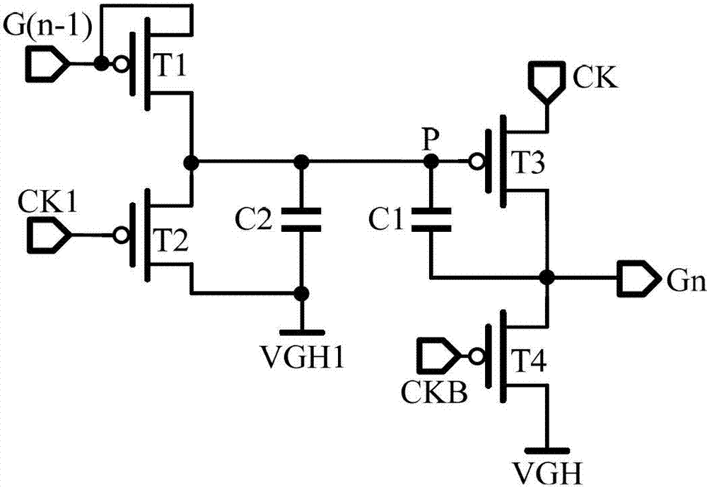
[0056] Such as Figure 6 As shown in , a shift register unit provided in this embodiment mainly includes: a pull-up module, connected to the first clock signal input terminal, the signal output terminal and the pull-up node P respectively, for The potential at the point P outputs the signal input by the first clock signal input terminal to the signal output terminal; the pull-down module is connected with the signal output terminal, the first signal terminal and the second clock signal input terminal respectively, and is used to input the signal according to the second clock signal The potential of the signal output terminal pulls down the signal output terminal; the pull-up drive module is connected to the signal input terminal and the pull-up node P respectively, and is used to drive the pull-up module according to the signal input from the signal input terminal; the reset module is respectively connected to the second signal Terminal, the second clock signal input end and t...


PUM


Abstract

The invention relates to the field of display technology, and particularly relates to a shift register unit and a driving method, a gate driving circuit as well as a display device thereof. Through arranging a voltage stabilizing capacitor which is connected with a pull-up node, the shift register unit provided by the embodiment of the invention stabilizes an electric potential at the pull-up node by using the voltage stabilizing capacitor, so that signals output by the shift register unit are more stable. Meanwhile, the shift register unit is composed of a small amount of transistors and capacitors, so that the wiring area of the gate driving circuit is greatly reduced, and a technical support is provided for designing a liquid crystal display device with a narrower border; in addition, the structure of the gate driving circuit is simplified, so that the manufacturing technology of the gate driving circuit is simplified, and the manufacturing cost is reduced. Furthermore, the shift register unit provided by the invention also fast and effectively pulls down the output signals to be a low electric potential through two pull-down processes; and the pull-down capacity of the gate driving circuit is strengthened.

Description

technical field [0001] The present invention relates to the field of display technology, in particular to a shift register unit, a gate drive circuit using the shift register unit, a driving method for driving the shift register unit, and a display device using the gate drive circuit. Background technique [0002] Thin Film Transistor Liquid Crystal Display (TFT-LCD) is widely used in televisions, mobile phones, monitors and other electronic products due to its advantages of stable picture, vivid image, radiation elimination, space saving and energy saving. It has occupied a dominant position in the field of flat-panel display. [0003] The liquid crystal display panel is composed of a matrix of pixels in both horizontal and vertical directions. When displaying, the gate driving circuit outputs a gate scanning signal to scan each pixel row by row. The drive of the liquid crystal display panel mainly includes a gate driver and a data driver. The data driver latches the input...

Claims


Application Information

Patent Timeline
IPC IPC(8): G09G3/36
CPCG09G3/20G09G2300/0465G09G2310/0267G09G2310/0286G11C19/184G11C19/28
Inventor 胡理科祁小敬
Owner BOE TECH GRP CO LTD
Learn More