
Super capacitor

A supercapacitor and electrode column technology, applied in the field of capacitors, can solve problems such as electrolyte leakage, seal damage, capacitor scrapping, etc., and achieve the effects of extending service life, tight contact, and easy cleaning.

Inactive Publication Date: 2016-03-02
北京华禹纵横科技有限公司
View PDF5 Cites 0 Cited by
  • Summary
  • Abstract
  • Description
  • Claims
  • Application Information

AI Technical Summary

Problems solved by technology

Since the existing supercapacitors are all assembled with shells and adsorption materials, such frequent changes cause serious deformation and damage to the end caps and shells, resulting in electrolyte leakage
Before the adsorption material of the supercapacitor fails, the shell and surrounding components are damaged, causing the entire capacitor to be scrapped in advance
[0003] Especially for large supercapacitors, the number of layers of the electrode group increases sharply, and the expansion and contraction caused by the adsorption and desorption process will be greatly superimposed, which is more likely to cause damage to the seal; when designing the structure, it is necessary to consider the resistance of the shell and the end cap. Pressure capacity, reliability of edge sealing, setting of pressure value, allowance for expansion and contraction, and limit the thickness error of each current collector, electrode, diaphragm, etc., even if there is a problem, maintenance and disassembly will Causes the destruction of the entire supercapacitor, which is very inconvenient

Method used


Image

  • Super capacitor
  • Super capacitor
  • Super capacitor

Examples


Embodiment 1

[0039] Embodiment 1, making a 20-layer electrode group and a rectangular supercapacitor

[0040] 1. Materials

[0041] 1. Electrode group material

[0042] Current collector: graphite paper, 0.5 mm thick, 18X25 cm, with a hole of ?10 in the center, 21 sheets;

[0043] Carbon electrodes: 18X18 cm, 0.5 mm thick, with a hole of ?10 in the center, 40 sheets;

[0044] Polyester mesh diaphragm: 0.15 mm thick, 20X20 cm, with a ?5 hole in the center, 20 sheets;

[0045] Cation separation membrane: 19X19 cm, 0.02 mm thick, with ?7 holes in the center, 20 sheets;

[0046] Anion separation membrane: 19X19 cm, 0.02 mm thick, with ?7 holes in the center, 20 sheets.

[0047] 2. Electrode column

[0048] ?10 through-wire titanium columns, 12 cm long, 6 pieces; ?10 hexagonal titanium nuts, 1 cm thick, 24 pieces.

[0049] 3. End cap

[0050] End cap: 30 cm long, 23 cm wide, and 3 cm thick, with honeycomb-shaped ribs (3 cm high). Correspondingly drill 2 rows of linear holes, each with 3...


PUM


Abstract

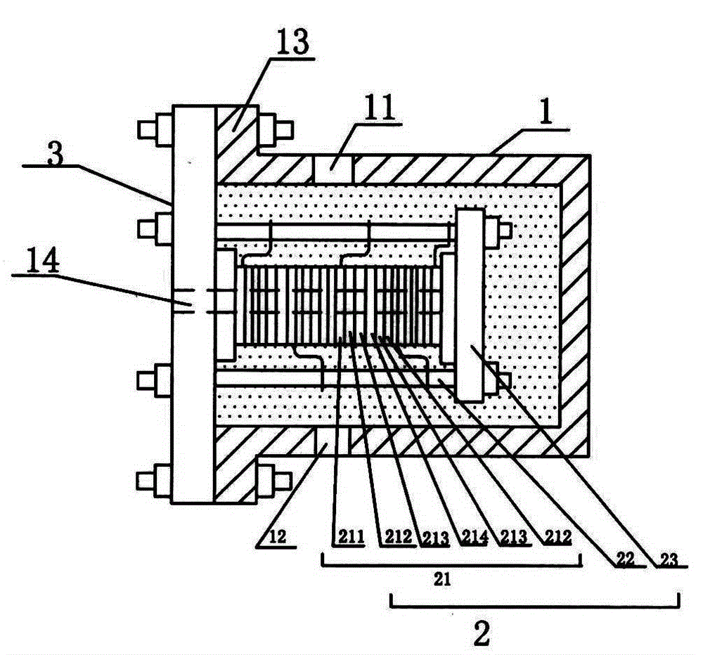
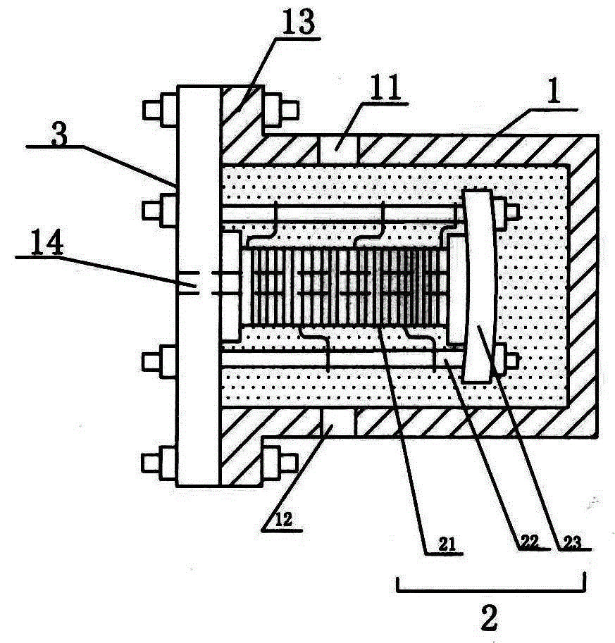
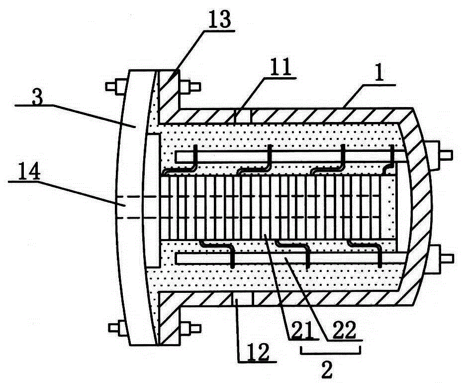
The invention discloses a super capacitor, which comprises a casing, a core body and an end cover, wherein the two ends of the casing are respectively provided with a water inlet and a water outlet communicated with an inner cavity of the casing, electrolyte is contained in the inner cavity of the casing, the core body is arranged in the electrolyte, the core body comprises electrode groups, an electrode post and a baffle plate, the electrode groups are penetrated and arranged on the electrode post in a staggered way, one end of the electrode post is screwed on the end cover, the other end of the electrode post is screwed on the baffle plate, the end cover is screwed on a flange arranged at the opening end of the casing, and a flow guide hole communicated with the inner cavity of the casing is arranged on the end cover. The core body of the super capacitor is completely independent from the casing and can be singly manufactured, the length of the core body can be freely set, and then, the casing with the matched length is adopted. The core body can singly adopt the ultra-high laminating pressure, so the contact of each layer of electrode array is tighter, the internal resistance is lower, the external deformation and the sealing do not need to be considered, the casing only bears the flowing pressure of the electrolyte, the deformation and the leakage are avoided, and the service life is greatly prolonged.

Description

technical field [0001] The invention relates to a capacitor, in particular to a super capacitor. Background technique [0002] Supercapacitor is a new type of energy storage device, which has the characteristics of short charging time, long service life, good temperature characteristics, energy saving and environmental protection. Supercapacitors are versatile: they can be used for energy storage, and they can also be applied to the adsorption and desorption of ions. Supercapacitors currently used for ion adsorption and desorption generally adopt the overall manufacturing and packaging method: the bottom of the supercapacitor shell is screwed with an electrode column, and several electrode groups are worn on the electrode column, and then the upper end cap is pressed on the electrode group. On the top, the end cover and the shell are screwed together to form an integrated structure. When the electrode group of this integrated supercapacitor is adsorbed and desorbed, due to...

Claims


Application Information

Patent Timeline
Patent Type & Authority Patents(China)
IPC IPC(8): H01G11/78H01G11/24
CPCY02E60/13
Inventor 李晓龙寇佩红王坤英孙严盛永刚盛照亮陆晓岩冯立军
Owner 北京华禹纵横科技有限公司
Learn More