Power storage system based on IEGT (injection enhanced gate transistor)

An energy storage system and energy conversion system technology, applied in the direction of AC network load balancing, etc., can solve the problems such as the difficulty of further improving the capacity and operating efficiency of a single machine, the limited withstand voltage and current resistance of IGBT devices, and the increased loss of IGBT devices. Achieve the effects of improving voltage tolerance, high operating frequency, and reducing on-state loss

Inactive Publication Date: 2013-11-20
ELECTRIC POWER RESEARCH INSTITUTE, CHINA SOUTHERN POWER GRID CO LTD
View PDF5 Cites 0 Cited by
  • Summary
  • Abstract
  • Description
  • Claims
  • Application Information

AI Technical Summary

Problems solved by technology

[0005] Although IGBT has made great progress compared with MOSFET and thyristor devices, and has greatly improved in terms of driving power and switching speed, its shortcomings are relatively obvious: (1) IGBT devices have limited withstand voltage and current resistance. The maximum withstand voltage of IGBT can reach the level of 1200V / 1700V, and the working current of the collector can reach 1200A. Due to the limitation of working voltage and current, the maximum capacity of a single PCS that can be produced in China is 500kW, which is difficult to further increase; (2) IGBT on-state The voltage drop has been significantly lower than that of MOSFET, but it is still relatively large. A large on-state voltage drop will increase the loss of the IGBT device in the on-state, so that it is difficult to improve the operating efficiency of the existing PCS based on the IGBT device to a satisfactory level. According to the current operating experience of energy storage systems, the theoretical maximum efficiency of single-stage PCS is about 97%, and the maximum efficiency of two-stage PCS is about 95%.
Due to the above shortcomings of IGBT, it is difficult to further improve the existing PCS stand-alone capacity and operating efficiency

Method used


Image

  • Power storage system based on IEGT (injection enhanced gate transistor)
  • Power storage system based on IEGT (injection enhanced gate transistor)
  • Power storage system based on IEGT (injection enhanced gate transistor)

Examples


Embodiment 1

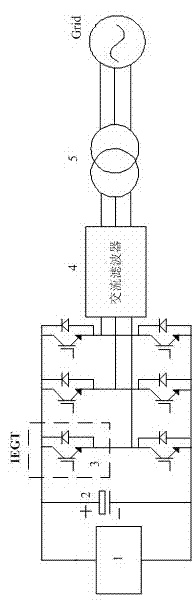
[0020] like figure 1 As shown, it is a schematic structural diagram of the IEGT-based energy storage system of the present invention, including a battery, an energy conversion system, a battery management system and a monitoring system. The battery, the battery management system and the monitoring system are general technologies and will not be described in detail. The present invention is mainly aimed at the improvement of the energy conversion system. The main loop structure of the energy conversion system in this embodiment adopts a DC / AC single-stage structure, and the specific structure is: the battery adopts a series-parallel connection to form a battery pack 1, and the battery pack 1 is connected in parallel with the DC capacitor 2 and connected to the DC / AC The DC side of the AC converter and the AC side of the DC / AC converter are connected to the AC filter 4 and the isolation / step-up transformer 5 in turn. All or part of the switching devices 3 of the / AC converter ...

Embodiment 2

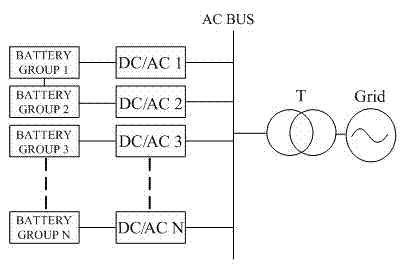
[0023] In order to facilitate the construction of energy storage systems of different power levels, the IEGT-based energy storage system of the present invention can also adopt the following structure: the basic structure is the same as that of Embodiment 1, and the difference is that the energy conversion system of the energy storage system of this embodiment has the same structure. The main loop structure is formed by connecting multiple single-stage DC / AC structures of the first embodiment in parallel. Its structure is figure 2 shown. The number of DC / AC units required in parallel can be set according to the required capacity of the system and the requirements for parallel connection of batteries.

Embodiment 3

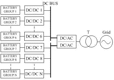
[0025] The structure of this embodiment is similar to that of Embodiment 1, except that the main circuit structure of the energy conversion system adopts a DC / DC+DC / AC two-stage structure; the battery adopts a series-parallel method to form a battery pack, and the battery pack is divided into N according to the capacity. The battery packs are respectively connected to the DC / DC converters of the front-stage DC / DC module. The voltage of each battery pack is converted into a unified DC voltage by the front-stage DC / DC module and then merged into the DC bus and used as the back-stage DC / AC module. The AC side of the DC / AC module is connected to the AC filter 4 and the isolation / step-up transformer 5 in turn, and the other end of the isolation / step-up transformer 5 is connected to the AC power grid. The two-stage topology can be used in the following three ways Realization: ① All or part of the switching devices of the DC / DC module use enhanced gate transistor devices, and the swit...


PUM


Abstract

The invention relates to the technical field of electronics, in particular to a power storage system based on an injection enhanced gate transistor (IEGT). By adopting the energy storage system, an IEGT device is used for replacing the current IGBT (insulated gate bipolar transistor) device in a power conversion system (PCS), the capacity of a single PCS is increased, the conduction loss is reduced, and the efficiency of the PCS is further improved.

Description

[0001] technical field [0002] The invention relates to the field of electronic technology, in particular to an energy storage system based on an enhanced gate transistor (Injection Enhanced Gate Transistor, IEGT). Background technique [0003] The energy storage system consists of a battery, an energy conversion system (Power Conversion System, PCS), a battery management system (Battery Management System, BMS) and a monitoring system. The energy conversion system is the core of the grid connection of the energy storage system, which realizes the bidirectional flow of energy between the energy storage system and the power grid, which directly affects the performance of the energy storage system. The main loop structure that PCS can adopt mainly includes DC / AC single-stage structure, DC / DC+DC / AC double-stage structure, H-bridge cascaded multi-level structure, etc. [0004] At present, the existing large-capacity PCS in China all use Insulated Gate Bipolar Transistor (IGBT),...

Claims


Application Information

Patent Timeline
Patent Type & Authority Applications(China)
IPC IPC(8): H02J3/32
Inventor 王科董旭柱雷金勇万庆祝郭晓斌
Owner ELECTRIC POWER RESEARCH INSTITUTE, CHINA SOUTHERN POWER GRID CO LTD
Why Eureka
Try Eureka