Energy-saving off-gas self-lazy circular sludge drying system and application method thereof

A sludge drying and self-inert technology, applied in separation methods, chemical instruments and methods, dehydration/drying/thickened sludge treatment, etc., can solve the problems of energy saving, environmental secondary pollution, etc., and achieve low investment and waste water The effect of small displacement and high comprehensive utilization rate of heat

Active Publication Date: 2013-11-27
TIANHUA INST OF CHEM MACHINERY & AUTOMATION
View PDF5 Cites 21 Cited by
  • Summary
  • Abstract
  • Description
  • Claims
  • Application Information

AI Technical Summary

Problems solved by technology

The disadvantages of the process are: ① After the boiler is incinerated and deodorized, a high-temperature waste gas of 500 °C is produced. There are three ways to treat the waste gas. One is to directly discharge the air, and the other is to use an indirect heat exchanger to heat the cold medium (such as air, process water, etc.) etc.) to recover heat, but the discharge temperature of high-temperature exhaust gas is also 200°C. The third is to use 20°C process water for direct spray cooling, and the exhaust gas discharge temperature can be controlled at 60°C, but a large amount of waste water at 60°C is produced. It is easy to cause secondary pollution to the environment; ②After drying, the 100°C high-humidity and odorous tail gas enters the boiler for incineration and requires fuel (such as coal, oil, natural gas, etc.) to provide the heat required for incineration, which is not energy-saving

Method used


Image

  • Energy-saving off-gas self-lazy circular sludge drying system and application method thereof

Examples


Embodiment Construction

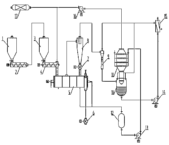
[0033] Such as figure 1 As shown, an energy-saving tail gas self-inert circulation sludge drying system includes a silo 1, a buffer silo 3 and a heat exchanger 11.

[0034] The top of the silo 1 is provided with a feed port I, and the bottom is provided with a screw pump 2, which is connected to the feed port II on the top of the buffer bin 3 through a pipeline I; the bottom of the buffer bin 3 is conveyed by a screw The device 4 is connected with a disc dryer 5; the bottom of one end of the disc dryer 5 is provided with a heating medium input pipe, the bottom of the other end is respectively provided with a dry sludge discharge port and a condensate discharge port, and the top is provided with an exhaust gas discharge port Ⅰ; the dry sludge discharge outlet is connected to the rotary unloader Ⅰ6 through the pipeline II; the condensate discharge outlet is connected to the condensate tank 12 through the pipeline Ⅲ, and the condensate tank 12 is connected to the heat exchanger 1...


PUM


Abstract

The invention relates to an energy-saving off-gas self-lazy circular sludge drying system. The system comprises a material cabin, a buffering cabin and a heat exchanger. The material cabin comprises a material inlet I and a screw pump, wherein the screw pump is connected with a buffering cabin material inlet II; the buffering cabin is connected with a disc drier; a heating medium input pipe, a dry sludge discharge port and a condensate discharge port are arranged at the bottom of the disc drier, and an off-gas discharge port I is formed in the top of the disc drier; the dry sludge discharge port is connected with a rotary unloading device I; the condensate discharge port is connected with a condensate tank connected with the heat exchanger; the off-gas discharge port I is connected with a separator connected with a rotary unloading device II and a Venturi dust collector; the rotary unloading device II is connected with the disc drier; the Venturi dust collector is connected with a cooler and a washing tank; the top of the washing tank is connected with a pipe VI, and the bottom of the washing tank is respectively connected with an effluent drainage pipe and a pipe VIII; the pipe VIII is connected with the cooler. Moreover, the invention discloses an application method of the system. According to the invention, investment is less, implementation is easy, and comprehensive utilization ratio is high.

Description

technical field [0001] The invention relates to the technical field of municipal sludge drying, energy saving, consumption reduction, and deodorization, in particular to an energy-saving tail gas self-inert circulation sludge drying system and an application method thereof. Background technique [0002] In the existing municipal sludge drying industrial plants, paddle dryers or disc dryers are mostly used as drying equipment, and the 100°C odorous and high-humidity tail gas after drying is mostly dusted by a cyclone separator and then discharged into a boiler for incineration and deodorization. The disadvantages of the process are: ① After the boiler incinerates and deodorizes, 500°C high-temperature waste gas is produced. There are three ways to treat the waste gas. One is to directly discharge the air, and the other is to use an indirect heat exchanger to heat the cold medium (such as air, process water, etc.) etc.) to recover heat, but the discharge temperature of high-te...

Claims


Application Information

Patent Timeline
Patent Type & Authority Applications(China)
IPC IPC(8): C02F11/12B01D50/00B01D53/02
Inventor 赵旭张麦奎申涛张万尧曹善甫王建刚杨喜龙王仕君郭雨徐瑞王磊
Owner TIANHUA INST OF CHEM MACHINERY & AUTOMATION
Why Eureka
Try Eureka